
Welcome back!!! We are now at Part two of the blog series on NSX-T architecture in vSphere with Tanzu. In this part, we will walk through the NSX-T architecture at scale of supervisor (workload) clusters and TKG clusters. We will deploy multiple supervisor clusters and namespaces and look at the two consumption options of Tier 0 Gateway – a shared Tier 0 model and a dedicated Tier 0 model.
This article is written based on vSphere 7.0Update1c, and as such per-Supervisor namespace based Tier 1 architecture is used for southbound connections to namespace segments and TKG clusters. If you missed Part1 where we spoke about per-TKG based Tier1 vs per-namespace based Tier1, please read it here:
This article is not meant for TKG Integrated Edition (formerly Enterprise PKS), I have added links to my previous articles on Enterprise PKS architecture at the end of the blog as an extra reading.
The terms ‘Supervisor cluster’ and ‘workload cluster’ are used interchangeably, both refers to the same cluster enabled with Workload management.
Let’s get started
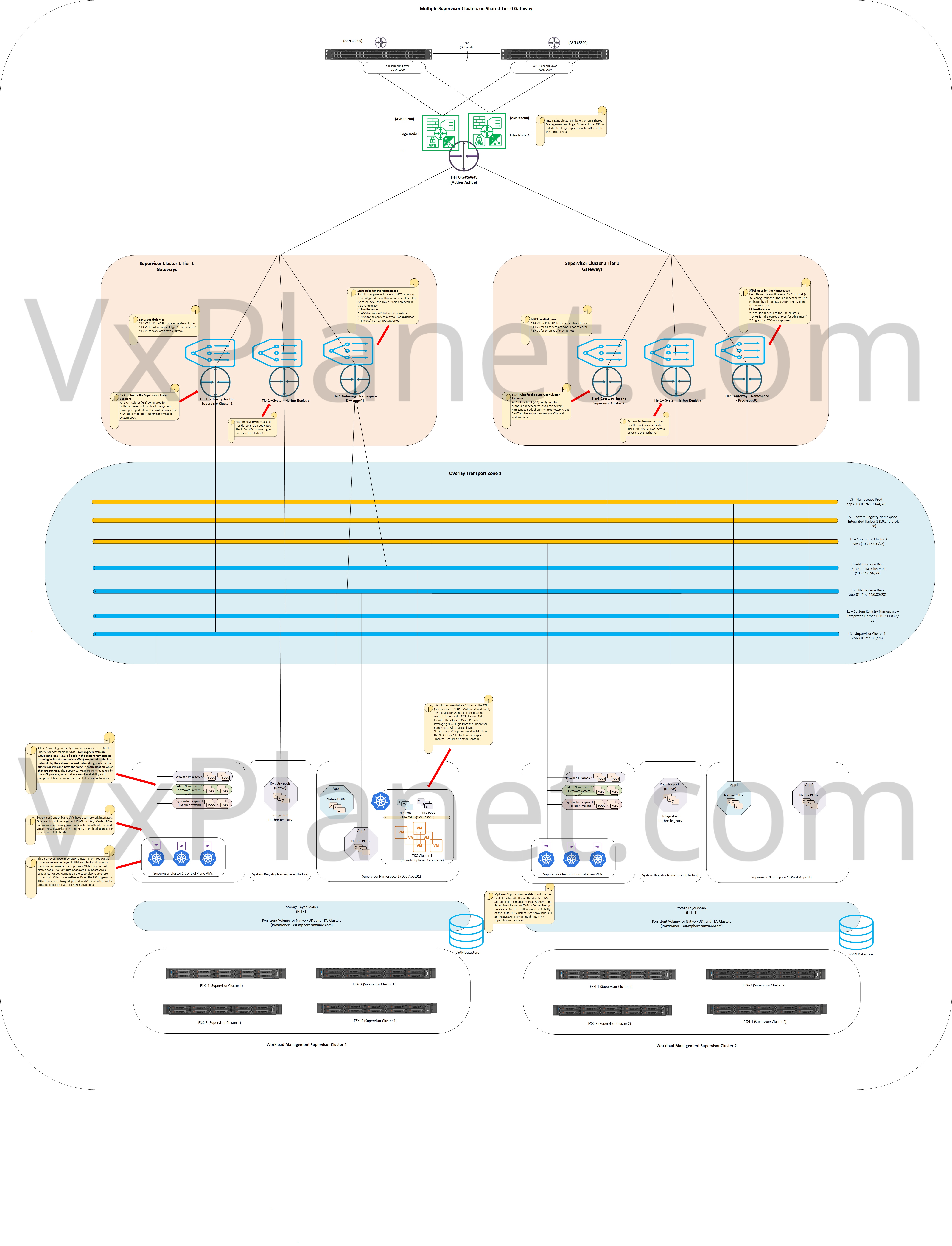
Multiple Supervisor Clusters on Shared Tier 0 Gateway
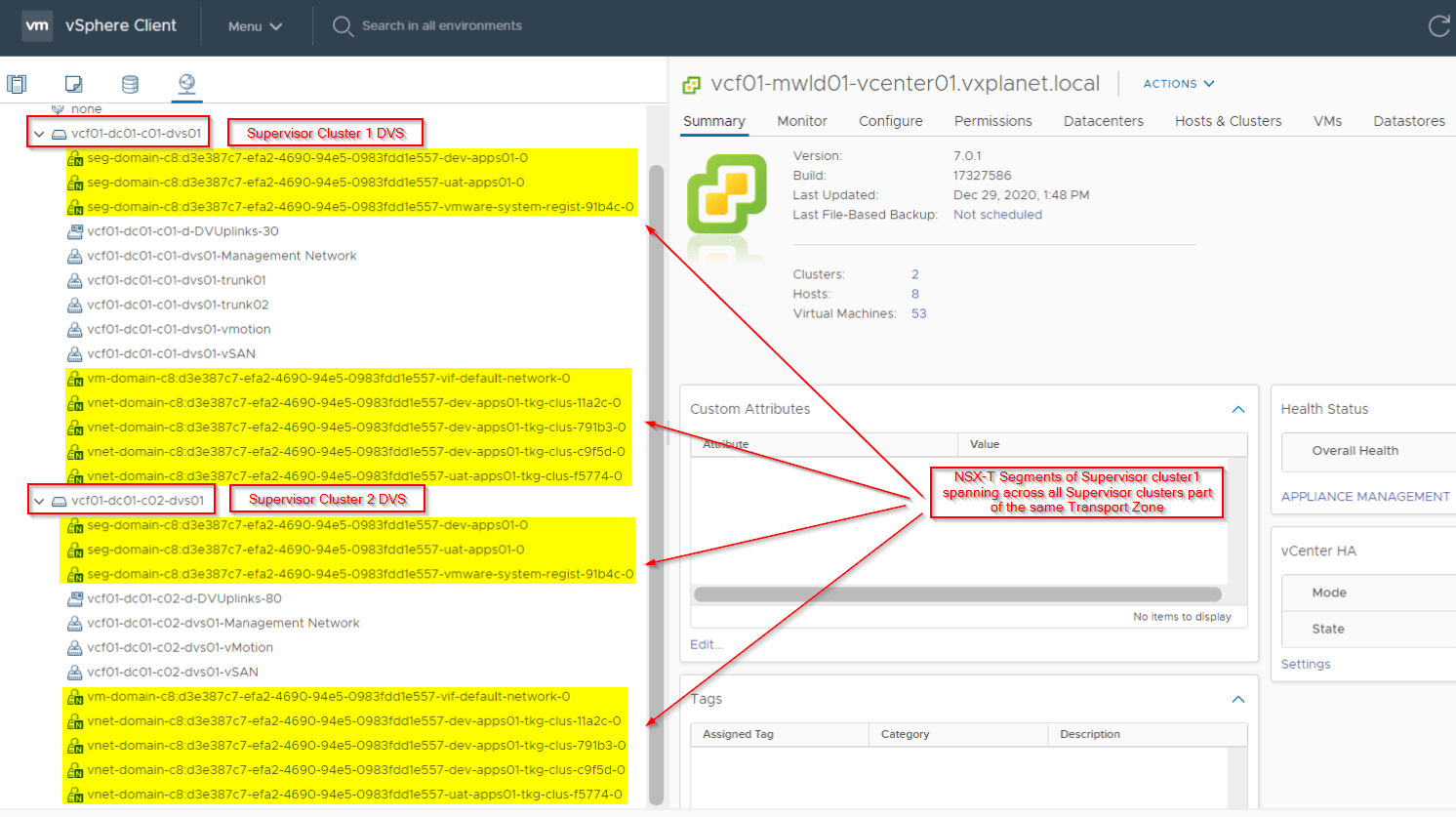
In this approach, additional supervisor clusters (workload clusters) share the same Tier 0 Gateway that was instantiated for the first supervisor cluster. All supervisor clusters are configured on the same Overlay Transport zone and logical Segments of each Supervisor cluster spans across all other supervisor clusters configured for that Overlay Transport zone. This is because the span of a logical Segment is decided by the span of the Overlay Transport Zone.
The supervisor clusters could be on same workload domain (single vCenter managed) or on multiple workload domains (multiple vCenter managed). Transport zone can span multiple vCenter domains added as compute managers.
Each supervisor (workload) cluster has physical isolation on the hardware resources but not on the logical networking. All the workload clusters appear to have pooled as a single logical entity on the NSX-T networking stack. All workload clusters have a common Ingress/Egress point northbound (same T0 Gateway).
This is a good model if we deal with Availability zones where the workload clusters map as Kubernetes availability zones. Availability zones based deployment is currently available only in the TKG Integrated Edition (Enterprise PKS) (and vanilla deployments) and not on vSphere with Tanzu platform. A deployment model where TKG clusters are decoupled from the underlying Supervisor namespace and spanned across multiple workload clusters (Availability zones) would require L2 adjacency for the VM placement like exactly how TKG Integration edition (formerly Enterprise PKS) does. This model also requires a shared storage available to all the Workload clusters for provisioning Persistent volumes.
[Click HERE for HQ image]
Pros:
- Simplified NSX-T architecture with savings in consumed vSphere resources, because we are not spinning up multiple Edge clusters. No additional BGP peerings and ASNs.
- Edge clusters reside either on the “Management and Edge vSphere cluster” or on the dedicated “vSphere Edge cluster” and are not co-located on the Workload cluster in most cases (with exceptions like VCF VI Workload domain). This makes all resources on the Workload cluster available only for Workload management use case.
- Inter-Supervisor cluster and TKG traffic is geneve encapsulated and not routed by the underlying physical fabric. All policy enforcements done within the NSX-T fabric.
- Per-Supervisor cluster specific Ingress/Egress CIDR pool helps trackability and observability.
- Supports Availability zones (future)
Cons:
- As all workload clusters belong to the same overlay Transport zone, segments span across each of them. No logical network isolation for the Supervisor clusters.
- A single edge cluster provides aggregate network resources for all the workload clusters (T1, Loadbalancers, NAT and other stateful services). Extra demand for network resources depends on the form-factor and scalability of the edge cluster (8 edge nodes currently). We can’t scale Edge clusters separately as per workload cluster requirements.
- Require dedicated pod cidr and service cidr for each supervisor cluster.
Multiple Supervisor Clusters on Dedicated Tier 0 Gateway
In this approach, additional workload supervisor clusters attach to dedicated Tier 0 Gateways. There are two deployment options depending on the level of logical network isolation:
- Dedicated T0 Gateways on separate Overlay Transport zones
- Dedicated T0 Gateways on shared Overlay Transport Zone
Multiple Supervisor Clusters on Dedicated Tier 0 Gateway (with logical network isolation)
In this approach, workload clusters are attached to dedicated Tier 0 Gateways on unique Overlay transport zones. As the span of Transport zone decides the span of a logical segment, each L2 segment of one workload cluster will confine to it’s vSphere cluster boundary. Each workload cluster now has physical isolation on the hardware resources and also on the logical networking. All workload clusters have dedicated Ingress/Egress point northbound (dedicated T0 Gateway).
This is a good approach at scale and for production workload clusters that need security and isolation from other workload clusters. This can’t be used for Availability zones (Kubernetes zones) in vSphere with Tanzu (future) that maps a workload cluster to a distinct AZ.
[Click HERE for HQ Image]

Pros:
- Each workload cluster maps to dedicated Overlay transport zones, and as such no overlapping of layer 2 logical segments.
- Edge cluster resources available exclusively for each workload cluster (T1, Loadbalancers, NAT and other stateful services) and can scale independently.
- Each workload cluster is visualized as a separate BGP ASN on the physical networking fabric. This give more PBR options on the physical fabric.
- Per-Workload cluster specific Ingress/Egress CIDR pool helps trackability and observability.
- Does not require dedicated pod cidr and service cidr for each supervisor cluster.
Cons:
- Additional resource requirements to accommodate the edge clusters.
- Additional BGP peering (and additional ASNs) for each Workload cluster that is provisioned.
- The edge cluster usually co-locates with the workload cluster (shared edge and workload cluster) so a portion of the workload resources are allocated to the edge cluster.
- Inter-Workload cluster traffic is not geneve encapsulated and routed by BGP between the physical fabric and edge nodes thereby putting a dependency on external routing over the physical fabrics.
- Concept of Availability zones doesn’t apply here.
Multiple Supervisor Clusters on Dedicated Tier 0 Gateway (without logical network isolation)
This can be thought of as a hybrid model between the first two approaches. Here, workload clusters are attached to dedicated Tier 0 Gateways and on a shared Overlay transport zone. The span of Transport zone decides the span of a logical segment, and as such L2 segments of workload clusters span to all other workload clusters. Each workload cluster has physical isolation on the hardware resources but not on the logical networking. This supports per-workload cluster specific Ingress/Egress (through the dedicated T0) as well as multi-Availability zone based shared Ingress/Egress (through any T0 in the fabric)
[Click HERE for HQ Image]

Pros:
- Edge cluster resources available exclusively for each Workload cluster (T1, Loadbalancers, NAT and other stateful services) and can scale independently.
- Each workload cluster is visualized as a separate BGP ASN on the physical networking fabric. This give more PBR options on the physical fabric.
- Per-Workload cluster specific Ingress/Egress CIDR pool helps trackability and observability.
- Does not require dedicated pod cidr and service cidr for each supervisor cluster.
- Supports Availability zones (future)
Cons:
- As all clusters belong to the same overlay Transport zone, segments span across each of them. No logical network isolation for the supervisor clusters.
- Additional resource requirements to accommodate the edge clusters.
- Additional BGP peering (and additional ASNs) for each Workload cluster that is provisioned.
- The edge cluster usually co-locates with the workload cluster (shared edge and workload cluster) so a portion of the workload resources are allocated to the edge cluster.
- Inter-Workload cluster traffic is not geneve encapsulated and routed by BGP between the physical fabric and edge nodes thereby putting a dependency on external routing over the physical fabrics.
Multiple Supervisor clusters in VMware Cloud Foundation 4.1
In VMware Cloud Foundation (VCF), the first cluster in a VI Workload domain (WLD) is a shared Edge and Workload cluster. All subsequent clusters spun up within the same VI WLD can be either:
- Workload only clusters that leverage the T0 gateway on the first cluster for Ingress/Egress.
- Workload + Edge cluster as per the Workload requirements.
In standard design, all clusters within the same VI WLD will be configured under the same Overlay Transport zone and the Workload management architecture can be either a shared Tier 0 model or a dedicated Tier 0 model (same overlay TZ). The diagram looks the same as before, but be aware that the edge cluster is co-located with the Compute (workload) cluster.
Note : VCF 4.1 didn’t allow multiple Edge Clusters in the same Overlay Transport Zone, that restricted us from using only the shared T0 Gateway model for the Workload clusters. This restriction has been lifted in version 4.1.0.1, allowing dedicated Tier 0 Gateways models for each Workload cluster.
Extra Reading – TKG Integrated Edition
To see how the NSX-T architecture looks like in TKG Integrated Edition (TKGI), formerly VMware Enterprise PKS, please read my previous articles below:
Shared Tier-1 Architecture :
https://vxplanet.com/2020/02/28/nsx-t-shared-tier-1-architecture-in-vmware-enterprise-pks/
Building NSX-T BYOT (Bring Your Own Topology) :
Now, it’s time to wrap time and will see in Part 3 where we discuss about dedicated Tier 1 Edge Clusters for vSphere with Tanzu.
I hope this article was informative.
Thanks for reading.
Continue reading? Here are the other parts in this series:
Part 4 : https://vxplanet.com/2021/02/12/nsx-t-architecture-in-vsphere-with-tanzu-part-4-proxy-arp-gateways/

One thought on “NSX-T Architecture in vSphere with Tanzu – Part 2 – MultiSupervisor Shared T0 vs Dedicated T0”