

Let’s continue the blog series on NSX-T architecture in vSphere with Tanzu. This is Part 4 and we will take a look at Proxy-ARP based deployment of NSX-T services for use with workload clusters.
In all the previous articles, we used a unique subnet (overlay based) for Ingress and Egress CIDRs for the workload clusters and TKGs and used BGP to advertise them to the ToR switches northbound. Proxy ARP based deployment doesn’t require any routing to be enabled between the Tier 0 Gateway and ToR switches and is ideal for Test and PoC environments. Proxy ARP based deployment is not recommended for production use cases as it supports only Active-Standby Tier 0 Gateways and don’t leverage BFD for faster failure detection and recovery.
To understand what Proxy ARP is, it is a technique where a router responds to ARP requests destined to devices attached to it’s different interfaces. In NSX-T, the Tier 0 gateway responds to ARP requests destined to the loadbalancers and NAT interfaces created on the Tier 1 gateway attached downstream. This way, a subset of the Tier 0 uplink subnet is carved out to provision the subnet for loadbalancers and NAT rules on the Tier 1 gateways, thereby completely eliminating routing between NSX-T edges and the ToR switches.
Proxy ARP doesn’t have any manual configuration, it is enabled by default whenever a loadbalancer VIP or NAT rule is created using an IP address from the subnet used on the Tier 0 interfaces.
vSphere with Tanzu architecture using Proxy ARP gateway
The below architecture shows a vSphere with Tanzu cluster leveraging a proxy ARP based NSX-T edge cluster. This is almost identical to the previous architectures except that:
- Routing is not involved in this architecture
- Tier 0 Gateways are deployed in Active-Standby form.
- Each edge node has only one uplink interface attached to the ToR switch (one interface VLAN only). Hence the Tier 0 gateway has 2 uplink interfaces in total, one over each edge node.
- A default static route (0.0.0.0/0) is configured on the T0 gateway which next-hops to ToR switch for northbound reachability.
- A single edge cluster is leveraged for both Tier 0 and Tier 1 gateways
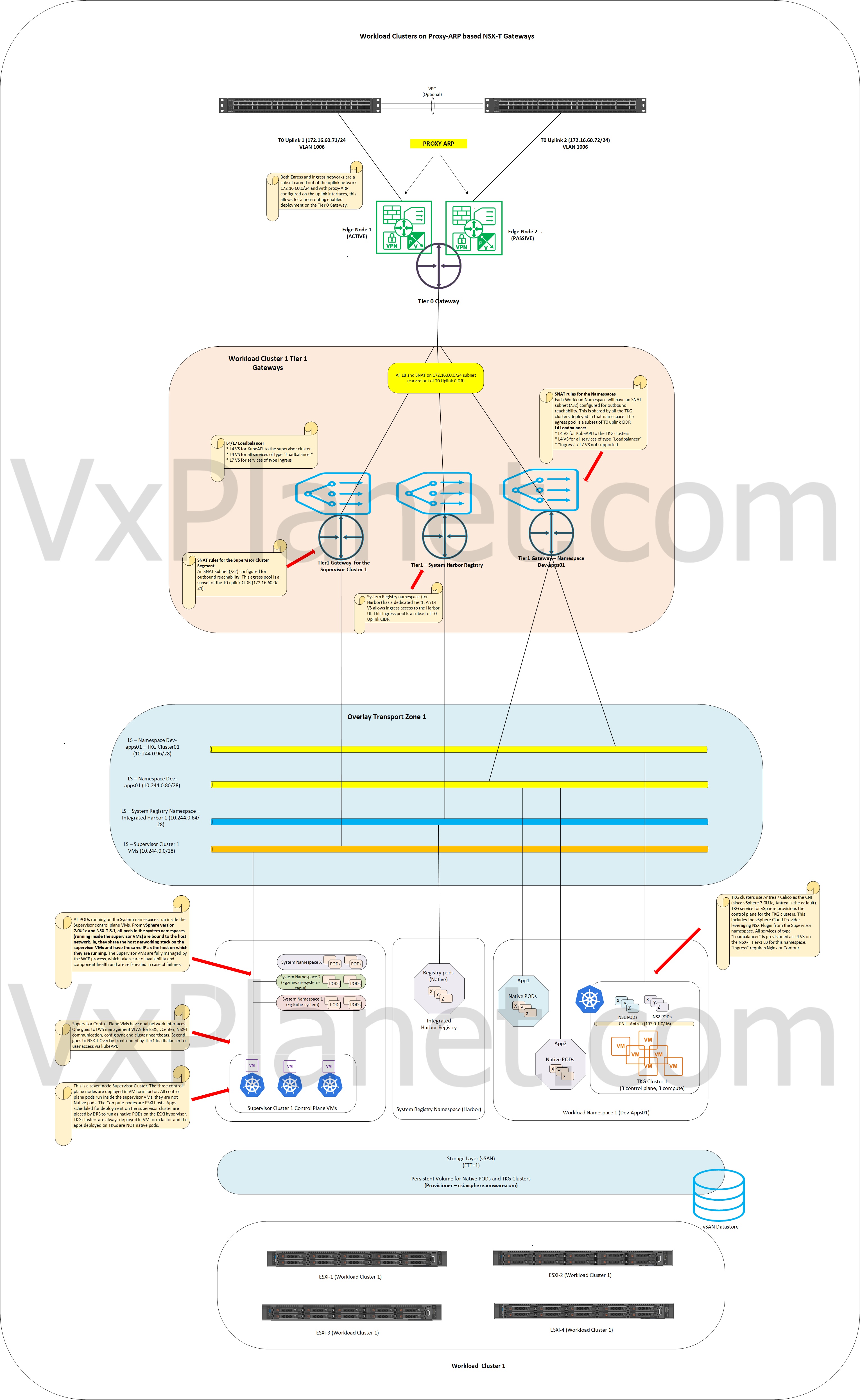
The above architecture uses a per-namespace Tier 1 topology, more details can be found on Part 1 :
Tier 0 Gateway configuration
As discussed earlier, only Active-Standby Tier 0 Gateways are supported for Proxy ARP. For the below T0, edge node ‘vcf01-mwld01-nsxedge05’ is Active and responds to proxy ARP requests from clients. The Standby node ‘vcf01-mwld01-nsxedge06’ won’t respond to Proxy ARP requests and will take over the role during edge failover


Configuring Workload Management to use Proxy ARP gateway
The Ingress and Egress CIDRs should be a subset of the subnet used on the Tier 0 Gateway interfaces. In our case this is carved out of 172.16.60.0/24. In other words, these CIDRs are VLAN based unlike previous deployments which are overlay based.


Once Workload management is configured, notice that the loadbalancer VIPs and NAT rules uses /32 IPs from the assigned pool.


By default, LB and NAT routes are advertised from the Workload cluster Tier 1 to the Tier 0 gateway, which is mandatory to enable Proxy ARP

Verifying Proxy ARP status and connectivity
Once the loadbalancer and SNAT rules are configured on the T1 gateway (using an IP address from the T0 uplink subnet), we should see Proxy ARP is enabled automatically on the T0 uplink interfaces of both Active and Standby Edge nodes. Only the Active edge node responds to proxy ARP requests, the standby edge doesn’t.


Active edge node sends gratuitous ARP to claim ownership for Proxy ARP request handling. Any clients trying to access the workload cluster or TKG will resolve ARP with the Active edge node.

As we can see, requests to kubeAPI (172.16.60.33) and NAT gateway (172.16.60.129) resolves to the mac of Active edge node uplink interface (00:50:56:82:95:d2 – 172.16.60.71)
During Edge node failover, the standby edge send gratuitous ARP to clients and starts responding to Proxy ARP requests. The failover isn’t quick as BFD, it completely depends on how and when the ARP tables are updated. For example, if there are 200 IP addresses where Proxy ARP is enabled, the standby node needs to send out 200 gratuitous ARP requests and get the tables updated.
Finally lets connect to the Workload Cluster over the Proxy ARP enabled Ingress IP

This concludes part 4 of the series. Will see you in Part 5 where we will discuss about the edge node networking with the converged DVS.
I hope the article was informative. Thanks for reading.
Continue reading? Here are the other parts of the series:
