
VMware Enterprise PKS Management Console recently got released to GA which provides an automated and unified way to deploy Enterprise PKS. This comes as an OVA appliance which is deployed on a management network and provides a very nice GUI to deploy Enterprise PKS components in a fully automated way. I started working on Enterprise PKS quite recently and my first deployment was a DIY following Pivotal documentation. This is a fully manual way of deployment and took almost half a day to finish an Enterprise PKS deployment. I liked the Enterprise PKS Management Console – We provide the necessary inputs along with the NSX-T BYOT information and the Management Console deploys and configures it all for us.
VMware Enterprise PKS Console supports three Networking Options:
- NSX-T (Automated deployment via Management Console)
- NSX-T Bring Your Own Topology (BYOT)
- Flannel

This multi-part blog series is about the second networking option – NSX-T Bring Your Own Topology (BYOT). It simply means this – Bring in an already existing NSX-T deployment or Create a supported NSX-T topology by ourselves and present it to Enterprise PKS Management Console for consumption.
Personally I like the BYOT approach because we get flexibility to configure the NSX-T environment based on our requirements. Even with the first option (Automated NSX-T Deployment), we have to meet the pre-requisites as well as do post-deployment configurations to satisfy our requirements like BGP, Route-maps & aggregation, Deterministic peering for the Edge nodes and so on.
Here are the contents of this multi-part blog series. I am not writing about the deployment step-by-step how-to, instead will do a walk through of all the NSX-T components and their configuration which I have already done for Management Console consumption.
Versions Used
- vSphere – 6.7 U3
- NSX-T – 2.5.0
- Enterprise PKS Management Console – 1.6.0
Part 1
- Environment Details
- NSX-T Manager Cluster
- Adding the Compute Manager
- Compute Hosts Uplink Profile
- Edge Uplink Profile for Tier 0 Gateway
- Edge Uplink Profile for Tier 1 Gateway
- Transport Zones – Overlay and VLAN
- Infrastructure VLAN Logical Segments
- Deterministic Traffic Steering for Infrastructure VLANs
- Edge T0 Uplink VLAN Logical Segments
- Deterministic eBGP Peering for the Edge nodes
Part 2
- Transport Node Profile
- Configuring Compute Clusters for NSX-T
- Realizing host NVDS in vCenter
- Configuring Edge Transport Nodes (T0)
- Configuring Edge Transport Nodes (T1)
- Edge Cluster (T0 & T1)
- Realizing the Edge Node Networking in vCenter
- vCenter Anti-Affinity Rules
- IP Blocks for Node Network & POD Network and Floating Pool Definition
Part 3
- Tier 0 Gateway
- BGP Configuration with Leaf Switches
- Route Summarization and Route-maps
- Verifying Route Advertisement
- PKS Management Network
Part 4
- Deploying the Enterprise PKS Management Console OVA
- Configuring Enterprise PKS Management Console and presenting NSX-T BYOT for consumption
- Deploying Enterprise PKS
Let’s get started
Environment Details
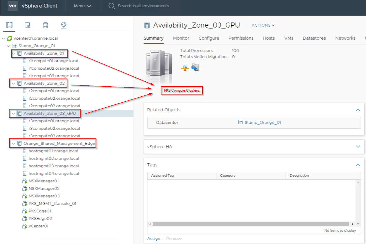
- Single vCenter, Single DataCenter with 4 Clusters
- Shared Management and Edge Cluster
- 3 X Compute Clusters which maps as Compute Availability Zones in Enterprise PKS
- All the ESXi hosts uses 2 x 10G pNIC networking.
- All Clusters use vSAN as the Distributed Storage
- There is a Shared NFS datastore available across all the clusters to store Persistent volumes for Kubernetes PODs.
- Shared Management and Edge Cluster uses vSphere DVS. It is not prepared for NSX-T
- All the three Compute Clusters are prepared for NSX-T. The hosts doesn’t have vSphere DVS and NVDS handles both Overlay and Infrastructure VLAN traffic
- Edge nodes are Single NVDS Multi-TEP attached to vSphere Trunk Port Groups on DVS on the Shared Management & Edge Cluster
- Separate Edge Clusters are used for Tier0 and Tier1 Gateways
- Anti-affinity rules are placed to avoid VMs of the same cluster ending up on the same ESXi host (NSX-T management cluster and Edge Cluster)
NSX-T Manager Cluster
3 x Manager Nodes with a Virtual IP set. As mentioned in the PKS Documentation below, if you are dealing with large number of Kubernetes clusters (>25), use a Loadbalancer as front end to the NSX-T Management Cluster. Good thing is that, using NSX-T Loadbalacers for NSX-T Management Cluster is supported.
https://docs.pivotal.io/pks/1-6/nsxt-install-mgmt-lb.html

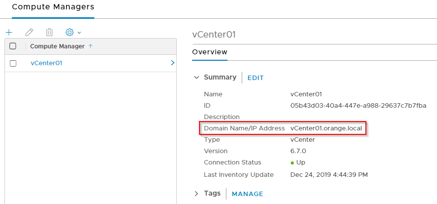
Compute Manager
vCenter is added as the Compute Manager
Compute Hosts Uplink Profile
The profile defines the Teaming Policies, TEP VLAN and MTU. Named teaming Policies are used for the vSAN, vMotion and Management traffic to achieve deterministic steering.

Edge Uplink Profile for Tier 0 Gateway
The profile defines the Teaming Policies, TEP VLAN and MTU. Named teaming Policies are used for the T0 Uplink VLAN Segments to achieve deterministic eBGP peering.

Edge Uplink Profile for Tier 1 Gateway
We don’t use Named teaming Policies here for the Tier1 Gateway Edges because it doesn’t have any VLAN Uplinks.

Transport Zones – Overlay and VLAN
Three Transport Zones are defined – One Overlay and Two VLAN leveraging the same NVDS. Compute Hosts and Edge nodes use separate VLAN Transport Zones to achieve isolation on the VLAN Logical Segments such that a VLAN logical switch (vSAN for eg.) meant for Compute hosts won’t be seen by the Edge nodes and vice-versa.

VLAN Transport Zone for the Compute hosts is updated with the Named teaming Policies defined in the Host Uplink Profile.

Similarly, VLAN Transport Zone for the T0 Edge nodes is updated with the Named teaming Policies defined in the T0 Edge Uplink Profile.

T1 Edge Nodes are configured only on the Overlay Transport Zone, so Named teaming Policies are not applicable to them.
Infrastructure VLAN Logical Segments
The necessary Infrastructure VLAN logical Segments are created on the Host VLAN transport Zone, so they are seen by the Compute hosts.

Deterministic Traffic Steering for Infrastructure VLANs
Named Teaming Policies defined in the Host Uplink Profile are applied to the VLAN Logical Switches.


Edge T0 Uplink VLAN Logical Segments
The T0 Uplink VLAN logical Segments are created on the Edge VLAN Transport Zone, so they are seen by the Edge nodes.

Deterministic eBGP Peering for the Edge nodes
Named Teaming Policies defined in the Edge T0 Uplink Profile are applied to the T0 Uplink VLAN Logical Switches.


At this moment, we are done with Part 1 and will continue the rest in Part 2.
I hope the article was informative. Thanks for reading.
Continue reading? Here are the other parts of this series:
