

VMware Enterprise PKS introduced the NSX-T shared Tier 1 architecture in NSX-T version 2.5. In this architecture, a Tier 1 Gateway is instantiated for each Kubernetes cluster (rather than for the namespaces) and all the stateful services are pushed down at the Tier 1 Gateway scope. This enables support for Tier 0 Gateway deployment in an Active-Active mode leveraging ECMP.
Earlier versions (prior to NSX-T Version 2.5) used a dedicated Tier 1 architecture where a Tier 1 Gateway is spun up for each Kubernetes namespaces. The result is that a given Kubernetes cluster will run several Tier-1 routers in this topology making the NSX-T console a bit messier. Here, Tier 0 Gateway runs all the stateful services and hence only Active-Standby deployment model is supported.
As said, we have the below deployment options for Enterprise PKS since NSX-T v2.5:
- Shared Tier 1 with Active-Active Tier 0 Deployment model
- Shared Tier 1 with Active-Passive Tier 0 Deployment model
- Dedicated Tier 1 with Active-Passive Deployment model
In this blog post, we will look at the Shared Tier 1 architecture with an Active-Active Tier 0 Gateway deployment mode. We will leverage the same platform as outlined in my earlier 4 part blog series, if you missed it you can read it from the below link:
Just an FYI, Dell EMC has a Ready Architecture Guide for Enterprise PKS on the VxRail platform. This covers the different sizing models for use cases, scalability and multi-rack deployments, if you are interested you can read it below:
Click to access pra-reference-architecture.pdf
Environment Details
Below is a quick summary of the platform deployed as per the previous articles outlined earlier.
- Single vCenter, Single DataCenter with 4 Clusters
- Shared Management and Edge Cluster
- 3 X Compute Clusters which maps as Compute Availability Zones in Enterprise PKS
- Shared Management and Edge Cluster uses vSphere DVS. It is not prepared for NSX-T
- All the three Compute Clusters are prepared for NSX-T. The hosts doesn’t have vSphere DVS and NVDS handles both Overlay and Infrastructure VLAN traffic
- Edge nodes are Single NVDS Multi-TEP attached to vSphere Trunk Port Groups on DVS on the Shared Management & Edge Cluster
- Separate Edge Clusters are used for Tier0 and Tier1 Gateways
- Tier 0 Gateway is deployed in Active-Active mode and eBGP is used to peer with the Leaf Switches (in VLT)
- PKS Management Console is deployed on vSphere DVS on the Shared Management and Edge Cluster.
- PKS Management Components (PKS API, OpsManager, BOSH, Harbor) are deployed on Availability Zone 1 with NAT enabled.
- All Kubernetes Nodes and PODs are deployed with NAT enabled for outbound access.
- Kubernetes Node & POD networks and Floating Pools are defined as below:
- K8S Node block – 172.31.0.0/16
- K8S POD Network – 172.30.0.0/16
- K8S Floating Pool – 192.168.105.0/24
Note : Currently all the K8S clusters deployed via PKS will leverage the same Edge Cluster used by the Tier 0 Gateway. We don’t have custom PKS Network Profiles that can leverage a dedicated Edge Cluster for Tier 1 Gateways. However the PKS Management Network uses a dedicated Edge Cluster for the Tier 1 Gateway.

Shared Tier 1 Logical Architecture

In Shared Tier 1 architecture,
- A Tier 1 Gateway is spun up for each Kubernetes cluster.
- Each Kubernetes namespace gets a dedicated Logical Segment.
- This Tier 1 Gateway is instantiated on an Edge Cluster. It shares the Edge cluster used by the T0 Gateway
- A Loadbalancer is instantiated on the Tier 1 Gateway with a VS (VIP) to accept KubeAPI requests for the Kubenetes Cluster.
- Any Kubernetes Service of Type Loadbalancer will be created as VS (VIP) on this NSX-T Loadbalancer.
- K8S Node network will have SNAT rules created (mapped to an IP on the Floating Pool) on the Tier 1 Gateway for outbound access
- Each K8S Namespace will have SNAT rules created (to an IP on the Floating Pool) on the Tier 1 Gateway for outbound access
- There is a no-SNAT rule between the K8S Node network and the PKS management network.
- DFW rules will be created as per K8S network policies.
Console Walk-through
Let’s see how this looks like in the console:
We’ll login to the PKS API and view the deployed K8S Clusters.
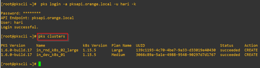
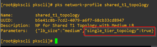
These two clusters are created using the PKS Network Profile for Shared T1 Gateway.
Let’s look at the cluster details for “in_rnd_k8s_02_large“

As highlighted,
- “Kubernetes Master IP” points to the VS in NSX-T Loadbalancer to handle KubeAPI requests (front-end)
- K8S Node and POD networks are non-routable with NAT enabled
Let’s connect to the cluster’s context.

Below are the K8S Namespaces – both system and custom.

Each namespace gets an NSX-T logical segment as shown below:
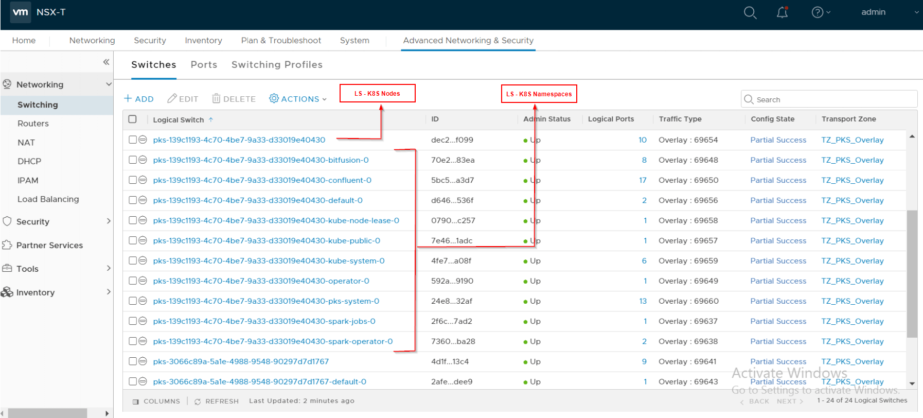
All of them attaches to the same Tier 1 Gateway. Below are the 3 Tier 1 Gateways deployed. Note that the Tier 1 Gateway for PKS Management is manually created prior to deployment.

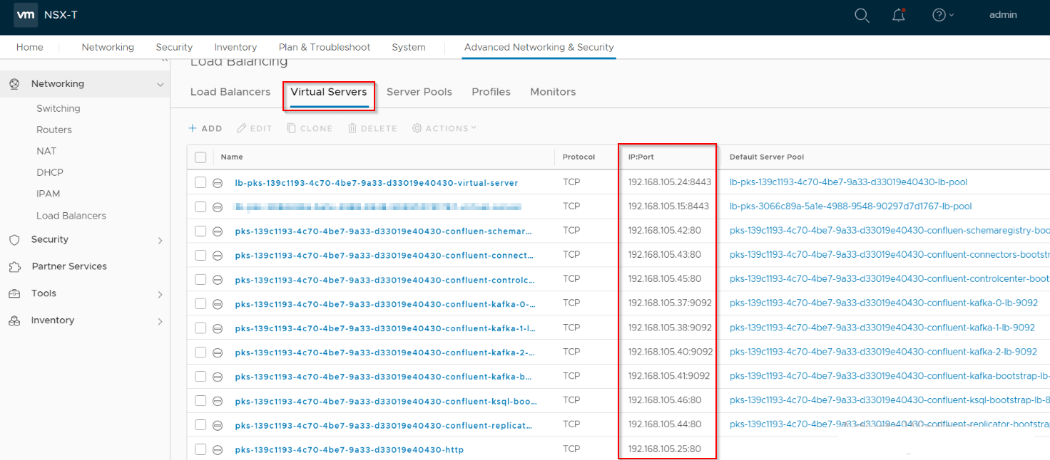
There is a dedicated Loadbalancer instantiated on the Tier 1 Gateway.

There is be a VS (VIP) on port 8443 to handle KubeAPI requests to the Kubernetes cluster. Any Kubernetes service of type Loadbalancer will be instantiated as VS on this Loadbalancer. Below you can see few VS (VIP) related to Confluent Platform application that I have deployed.
Let’s look at the NAT rules created for K8S Cluster:
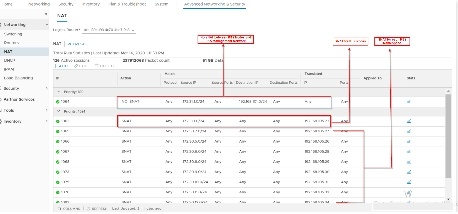
- An SNAT rule is created for the K8S nodes
- An SNAT rule is created for each K8S Namespaces
- A /32 IP is taken from the Floating Pool for the SNAT translation
- A no-SNAT rule is created between the K8S Nodes and the PKS Management Network.
Let’s look at the NAT rules created for the PKS Management Network:
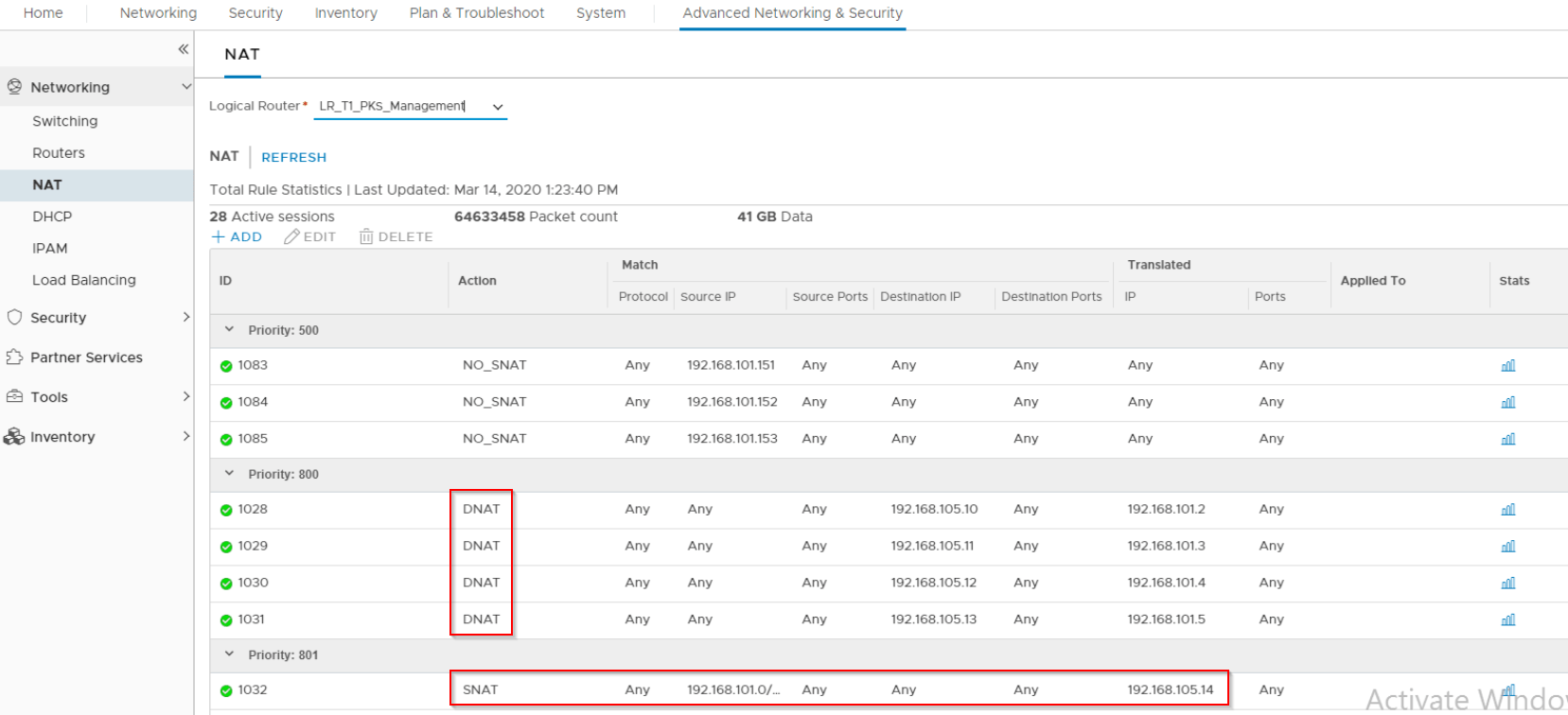
- AN SNAT rule is created for the PKS Management Network
- DNAT rules are created for access to BOSH, PKS API, Ops Manager and Harbor access
We also see that no stateful services are deployed on the Tier 0 Gateway

Dedicated Tier 1 Logical Architecture (prior to NSX-T v2.5)
Prior to NSX-T 2.5, this was how the architecture looked like:

- A Tier 1 Gateway is spun up for each Kubernetes Namespace.
- Each Kubernetes namespace gets a dedicated Logical Segment connected to its dedicated Tier 1 Gateway.
- The Tier 1 Gateway for the K8S Nodes and PODs are not instantiated on the Edge Cluster, they have only a DR Construct.
- Loadbalancers are instantiated on a separate Tier 1 router and with a separate logical segment. This Tier 1 Gateway is instantiated on an Edge Cluster. It shares the Edge cluster used by the T0 Gateway.
- Each Loadbalancer is specific to the K8S cluster.
- This Loadbalancer is instantiated with a VS (VIP) to accept KubeAPI requests to the K8S cluster
- Any Kubernetes Service of Type Loadbalancer will be created as VS on this NSX-T Loadbalancer
- K8S Node network will have SNAT rules created (to an IP on the Floating Pool) on the Tier 0 Gateway for outbound access
- Each K8S Namespace will have SNAT rules created (to an IP on the Floating Pool) on the Tier 0 Gateway for outbound access
- There is a no-SNAT rule between the K8S Node network and the PKS management network.
- DFW rules will be created as defined in K8S network policies.
- Tier 0 Gateway is always deployed in Active-Standby mode.
I hope this article was informative.
Thanks for reading
