
This is the second part of the 4-part blog series on ‘Building an NSX-T Bring Your Own Topology (BYOT) for VMware Enterprise PKS’. In case you missed Part 1, here is the link:
Here are the contents of this article. As said earlier, this is not about the deployment step-by-step how-to, instead will do a walk through of all the NSX-T components and their configuration which I have already done for Management Console consumption.
- Transport Node Profile
- Configuring Compute Clusters for NSX-T
- Realizing host NVDS in vCenter
- Configuring Edge Transport Nodes (T0)
- Configuring Edge Transport Nodes (T1)
- Edge Cluster (T0 & T1)
- Realizing the Edge Node Networking in vCenter
- vCenter Anti-Affinity Rules
- IP Blocks for Node Network & POD Network and Floating Pool Definition
Let’s get started.
Transport Node Profile
All the Compute Clusters are prepared for NSX-T using Transport Node Profiles. This is to allow consistency in the configuration as well as for automatic configuration of Transport Nodes whenever a Compute Cluster is scaled out with additional hosts. All the Compute hosts use 2 pNIC networking, using Transport Node Profiles help in easy and consistent migration of host networking to NVDS. For more details, please visit my earlier article at the below link:

All Compute hosts are configured on an Overlay and a VLAN Transport zone. We have already applied Named Teaming Policies on this VLAN Transport Zone.

We will specify mappings for the pNICs here. Each pNIC maps to the logical uplink construct on the NVDS. Since the pNICs are already bound to the vmk interfaces on the vSphere DVS networking, make sure to uncheck “pNIC only migration”. This option is used only if there are no vmk interfaces associated with the pNIC to be migrated to NVDS.

In order to migrate the vmkernel ports, we have to define mappings under “Network Mappings for Install”. This is a 1:1 binding between a vmkernel portgroup to NVDS Logical Segment. As a note, confirm that the VLAN Logical Segments have the same VLAN identifier as the vmkernel portgroup to be mapped.

If for some reasons, we need to unprepare the cluster from NSX-T and revert to the vSphere DVS networking, we have to define the mappings under “Network Mappings for Uninstall”. This is because NSX-T manager doesn’t maintain any network mapping tables. In our case we don’t need it as the compute clusters are on a 2-pNIC networking, but this is how we have to define it.


Configuring Compute Clusters for NSX-T
All the three Compute Clusters are configured for NSX-T using the Transport Node Profile. All of them use NVDS for both Overlay and Infrastructure VLAN traffic. The vSphere DVS has been disassociated from the Compute Transport nodes. Note that the Shared Management & Edge Cluster is NOT prepared for NSX-T. It is on vSphere DVS.

Realizing host NVDS in vCenter
This is the final state of a Compute host network. All infrastructure VLAN and Overlay traffic are on NVDS with deterministic steering over the two pNIC uplinks.

Configuring Edge Transport Nodes (T0)
We have dedicated Edge Clusters for T0 and T1 Gateways.

Edge nodes for T0 Gateway are configured on both Overlay and VLAN Transport Zones. The deployment model is Single NVDS Multi-TEP

The Edge uplinks attach to Trunk Port Groups on vSphere DVS on the Shared Management & Edge Cluster.

Configuring Edge Transport Nodes (T1)
Edge nodes for T1 Gateway are configured only for Overlay Transport Zone. The deployment model is Single NVDS Multi-TEP

The Edge uplinks attach to Trunk Port Groups on vSphere DVS on the Shared Management & Edge Cluster.

Edge Cluster (T0 & T1)
We have two Edge Clusters – One for T0 gateway and the other for T1 Gateway

Realizing the Edge Node Networking in vCenter
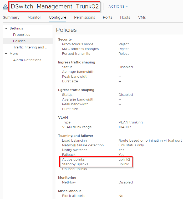
As mentioned earlier, the Edge nodes attach to Trunk Port Groups on vSphere DVS on the Shared Management & Edge Cluster.

The Trunk Port Groups have failover teaming policy set with alternating Active and Passive Uplinks. Named Teaming Policies on the Edge Uplinks along with failover teaming policies on the vSphere DVS trunk Port Group helps in achieving deterministic eBGP peering over the pNICs.

vCenter Anti-Affinity Rules
Three DRS VM/Host anti-affinity rules are in place on the Shared Management and Edge Cluster:
- For the NSX Manager VMs
- For the T0 Edge VMs
- For the T1 Edge VMs


IP Blocks for Node Network & POD Network and Floating Pool Definition
The PKS subnets are defined in NSX-T prior to deployment
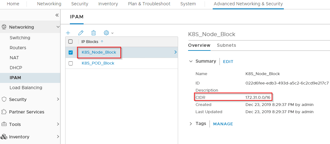
Node Network – This is the network will be used by the Kubernetes nodes which are deployed by PKS BOSH Director. We will define a /16 pool here and PKS will carve a /24 block out of it and NSX-T manager will associate this to a dedicated Tier 1 Segment. The node network used in this setup is 172.31.0.0/16. This is a routable subnet.
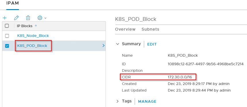
POD Network – This is the network that will be used by each Kubernetes namespace. We will define a /16 pool here and PKS will carve a /24 block out of it and NSX-T manager will associate this to a dedicated Tier 1 Segment. All PODs on the same namespace attach to the same Logical Segment. The POD network used in this setup is 172.30.0.0/16. This is a non-routable subnet. So a NAT instance is needed for for the PODs for external access.
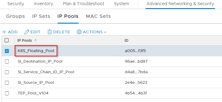
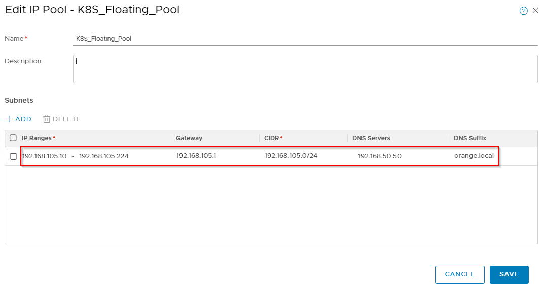
Floating Pool Network – This is a routable block that will be used for SNAT instances and Loadbalancer VIPs. We will define a /24 block and NSX-T will carve a /32 IP out of it. This is used whenever a Loadbalancer instance is required for Kubernetes (like LB for KubeAPI, Ingress Controller etc) as well as for SNAT instances for POD networks. The floating pool network used in this setup is 192.168.105.0/24
We are now done with Part 2 and will continue in Part 3. I hope the article was informative. Thanks for reading.
Continue reading? Here are the other parts of this series:
