
This is Part 3 of the 4-part blog series on ‘Building an NSX-T Bring Your Own Topology (BYOT) for VMware Enterprise PKS’. In case you missed Part 1 and 2, here are the links:
Here are the contents of this article:
- Tier 0 Gateway
- BGP Configuration with Leaf Switches
- Route Summarization and Route-maps
- Verifying Route Advertisement
- PKS Management Network
Let’s get started:
Tier 0 Gateway
A Tier 0 Gateway is deployed in Active-Active mode leveraging the dedicated T0 Edge Cluster. Active-Active T0 Gateway is supported only from NSX-T version 2.5 onwards where the stateful services are pushed down to the respective Tier 1 Gateway using a Shared T1 topology. In a Shared Tier1 architecture, a dedicated T1 Gateway is deployed per Kubernetes cluster rather than per namespace (prior to v2.5). Kubernetes clusters are deployed using PKS Network Profiles to achieve this.
T0 Active-Active mode is actually not a requirement for Shared T1 architecture, we will use it to achieve ECMP for our topology.

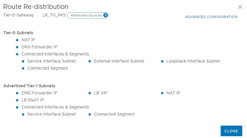
This is the route redistribution criteria on the T0 Gateway. All stateful services are deployed on Tier 1, so the necessary NAT IPs, LB VIPs etc which are advertised from the T1 Gateway are redistributed into the BGP process.
BGP Configuration with Leaf Switches
The Tier 0 Gateway has 4 interfaces – two via Edge node 1 (PKSEdge01) and other two via edge node 2 (PKSEdge02)
It has 4 eBGP peering with two Leaf Switches in VLT over two VLANs (VLAN 106 & 107)
BFD is enabled on the BGP process to achieve quick failure detection and faster convergence.
T0 Gateway is in AS number 65400 and Leaf Switches are on AS 65500

This is the BGP Neighborship table from one of the Edge nodes.

The first entry in the table is the Inter-SR iBGP link established between the Edge nodes to handle asymmetric failures on the uplinks.
Route Summarization and Route-maps
When a Kubernetes cluster is deployed by PKS, all the T1 Gateways for the Kubernetes nodes and the necessary segments for PODs are created and configured automatically and they attach to the T0 Gateway. The subnets on the T1 Gateway are advertised (auto-plumbed routes) to the T0 Gateway which is redistributed into the BGP process and is received by the ToR Leaf Switches. The advertised networks include Kubernetes node network, POD network and the Floating networks used on the LB and NAT instances. Some observations:
- PKS will carve a /24 block out of the 172.30.0.0/16 pool for the POD network and the POD subnets are advertised in BGP as /24 networks. This creates a lot of entries in the BGP routing table as namespaces grows, which is unnecessary
- If we don’t want the POD network to be on a routable subnet and use NAT instead, then we need to avoid advertising the POD subnet 172.30.0.0/16
- PKS will carve a /24 block out of the 172.31.0.0/16 pool for the Kubernetes node network and are advertised in BGP as /24 networks. This creates a lot of entries in the BGP routing table as kubernetes cluster grows, which is unnecessary
- PKS will carve a /32 IP out of the 192.168.105.0/24 pool for the Floating network used for LB and NAT instances and are advertised in BGP as /32 networks. This again makes the routing table entries messier.
We use Route Aggregation and Route maps to simplify the route advertisement and keep the routing tables shorter and easy to read and understand. A more explanation around this is covered in my earlier article below:
https://vxplanet.com/2019/11/30/bgp-considerations-in-nsx-t-integrated-vmware-enterprise-pks/
Route Aggregation
We will aggregate the POD and Node networks to /16 and the Floating Pool ranges to /24. We will also enable the “Summary-Only” flag which will advertise only the aggregated routes and suppresses the more specific routes.

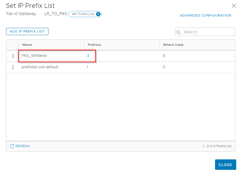
Prefix-List
We will set up a Prefix-list to match only the networks that we need to advertise. Depending on whether we need a routable POD subnet, we may include or exclude them from the Prefix-list whitelist.

Route-maps
We will now define a Route-map and match the Prefix-list that we created just before. There is an explicit “Deny” at the end of Route-map so we don’t need to define a separate deny Prefix-list.
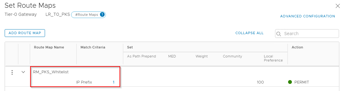
We will apply this Route-map as an Outbound filter to the BGP neighbor interfaces.

Verifying Route Advertisement
We will advertise some dummy 192.168.105.0/32 networks from the T0 Gateway and should see that they are aggregated to /24 mask on the Leaf Switches.

This confirms the T0 Gateway Active-Active configuration along with BGP considerations for Enterprise PKS.
PKS Management Network
While using Enterprise PKS Management Console to deploy PKS, have a look at the supported configurations for the PKS Management network in the below Pivotal documentation:
https://docs.pivotal.io/pks/1-6/console/ova-deployment-prereqs.html
Deployments to a No-NAT topology for the PKS Management Network with a vSphere Standard Switch or a vSphere Distributed Switch is not supported. The PKS Management Network (NAT or no-NAT) should be on an Overlay Tier 1 Gateway attached to the T0 Gateway.
We could either have a dedicated AZ for PKS Management (configured for Overlay) or could share Compute AZ1 for the PKS Management & Control plane VMs. Let’s use the Shared Compute AZ1.
This is the dedicated Tier 1 Gateway for the PKS Management network.
Note: If we use NAT Mode for the PKS Management, make sure to select the T1 Edge Cluster to host the stateful services. A /32 subnet is carved from the Floating Pool network 192.168.105.0/24 for the necessary SNAT and DNAT rules for the PKS Management Network. DNAT rules are created for inbound access to the Ops Manager WebUI, PKS API, Harbor etc and SNAT rules for outbound access from these VMs.
This Tier1 Gateway is linked to the Tier0 Gateway. Since the PKS Management subnet is non-routable, it is not added to the Prefix list for Whitelisted networks in BGP advertisement.

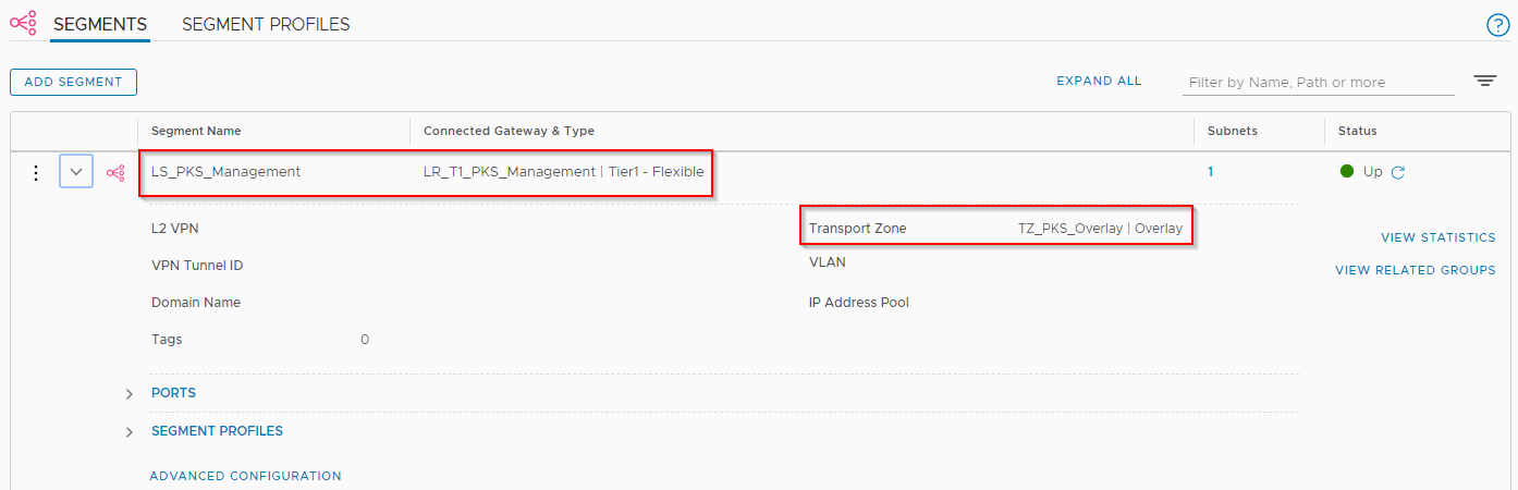
This is the segment defined for PKS Management network. The subnet used is 192.168.101.0/24 (non-routable).
We are now done with Part 3. In the next and final part, we will deploy Enterprise PKS using the Enterprise PKS Management Console and present this NSX-T Infrastructure as BYOT for consumption.
I hope the article was informative. Thanks for reading.
Continue reading? Here are the other parts of this series:
