

Welcome back!!! We are at Part 10 of the blog series on NSX-T Federation.
In all the previous articles, we leveraged a shared edge cluster for stretched T0/T1 gateways and packet walks. Now let’s introduce a dedicated edge cluster for stretched Tier 1 Gateways and see how the northbound routing and ECMP gets influenced with this design.
This has been a lengthy series, if you were not following along and want to start from the beginning, I have added links to the previous articles at the end of this blog post.
Let’s get started.
Current Environment
The topology used is a stretched Active-Active Tier 0 Gateway with location Primary – Secondary spanned across three locations – Site A ,B & C with Site A as the primary location. To see the full configuration of the stretched Tier 0 Gateway, please visit Part 4 of this series.
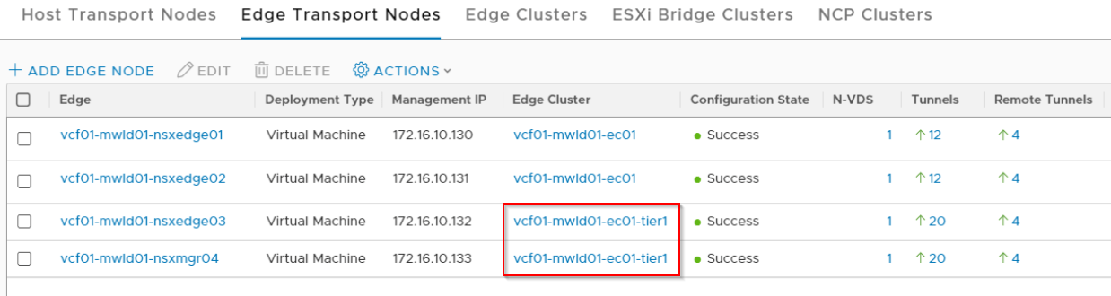
Let’s introduce a new edge cluster for T1 Gateways in Site A. Site B and C will still run with a shared T0/T1 edge cluster. We will create two Tier 1 gateways from the GM.
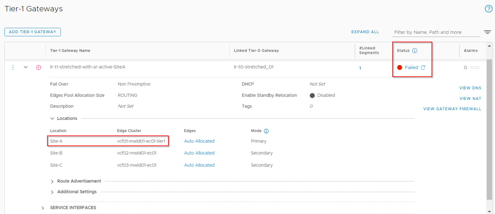
- lr-t1-stretched-with-sr-active-siteA -> This is a stretched T1 gateway with SR primary on Site A and spans all the three locations.
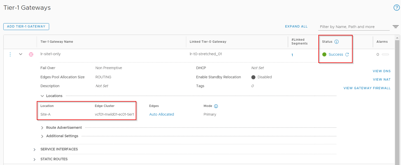
- lr-t1-siteA-only -> This is a non-stretched T1 gateway on Site A.
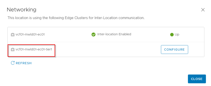
Below is the T1 edge cluster on Site A.
T1 Edge cluster without RTEP configuration?
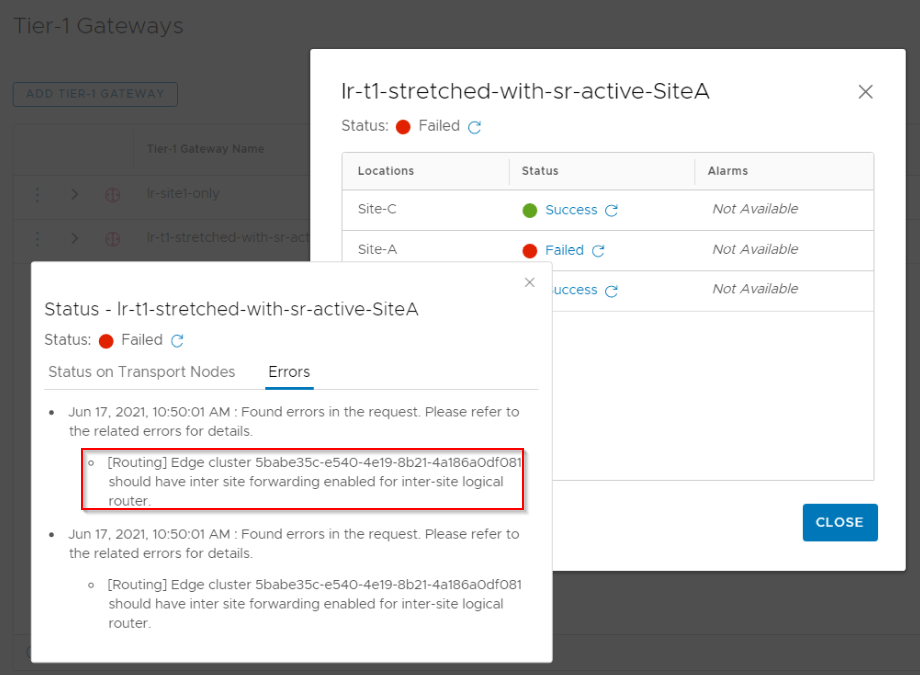
If the T1 edge cluster doesn’t have an RTEP configuration, we can create only non-stretched T1 Gateways (span of local site). This is because a stretched logical segment attached to this T1 Gateway with SR requires a VTEP Group, L2forwarder and an RTEP group to build the control plane for L2 forwarding across locations. Let’s test this by creating the above mentioned T1 gateways.
- Non-stretched T1 gateway with SR (on Site A) is successfully realized and we have reachability from and to ToR networks.
- Stretched T1 gateway with SR primary on Site A is unsuccessful for Site A and successful for Site B & C. This is because Site B & C already uses a shared T0/T1 edge cluster that has RTEP configured.
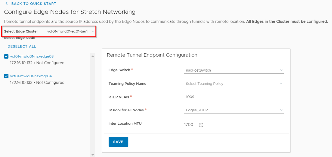
Configuring RTEP for the T1 Edge Cluster
T1 edge cluster is part of two transport zones – Overlay transport zone (same as other transport nodes) and an internal RTEP VLAN transport zone. The RTEP VLAN transport zone is auto-assigned during RTEP configuration.
RTEPs can be configured directly on the edge nodes from the LM or via the GM

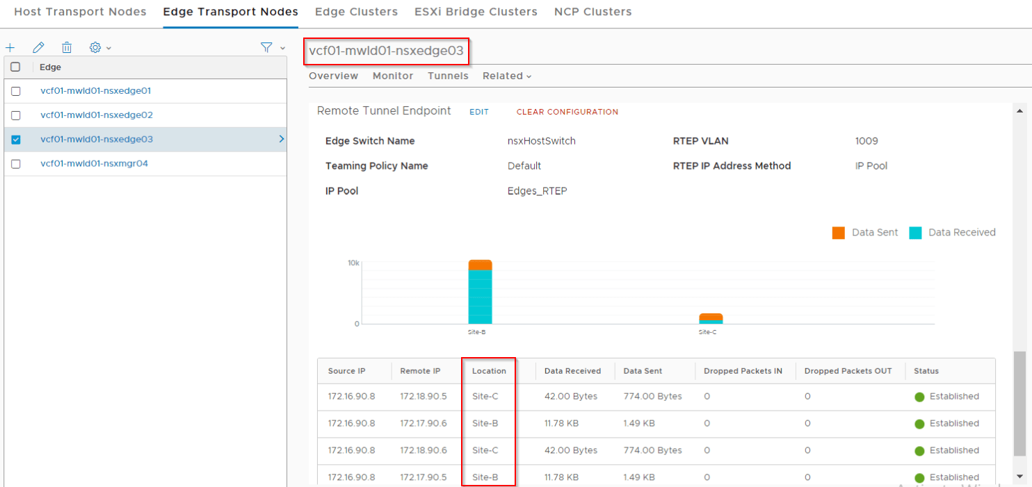
Once RTEP configuration has succeeded, we should see RTEP tunnels established to other locations from the T1 edge cluster.
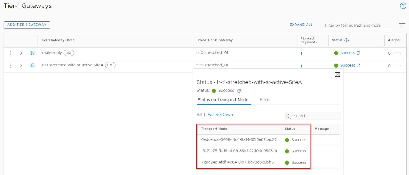
Now if we deploy the stretched T1 gateway with span across all the three locations, this should succeed.
Northbound routing and ECMP
In all of the previous packet walk articles, we used a shared T0/T1 edge cluster and hope you might have noticed that we had fewer ECMP options northbound whenever a T1 SR construct is involved in the data path. This is because edges always prefer local forwarding and traffic will try to egress out of the T0 SR uplinks on the edge node after a T1 SR lookup locally. This behavior changes in a dedicated T1 edge cluster design where the traffic is TEP tunnelled to the T0 edge cluster for egress. Let’s take a closer look at this.
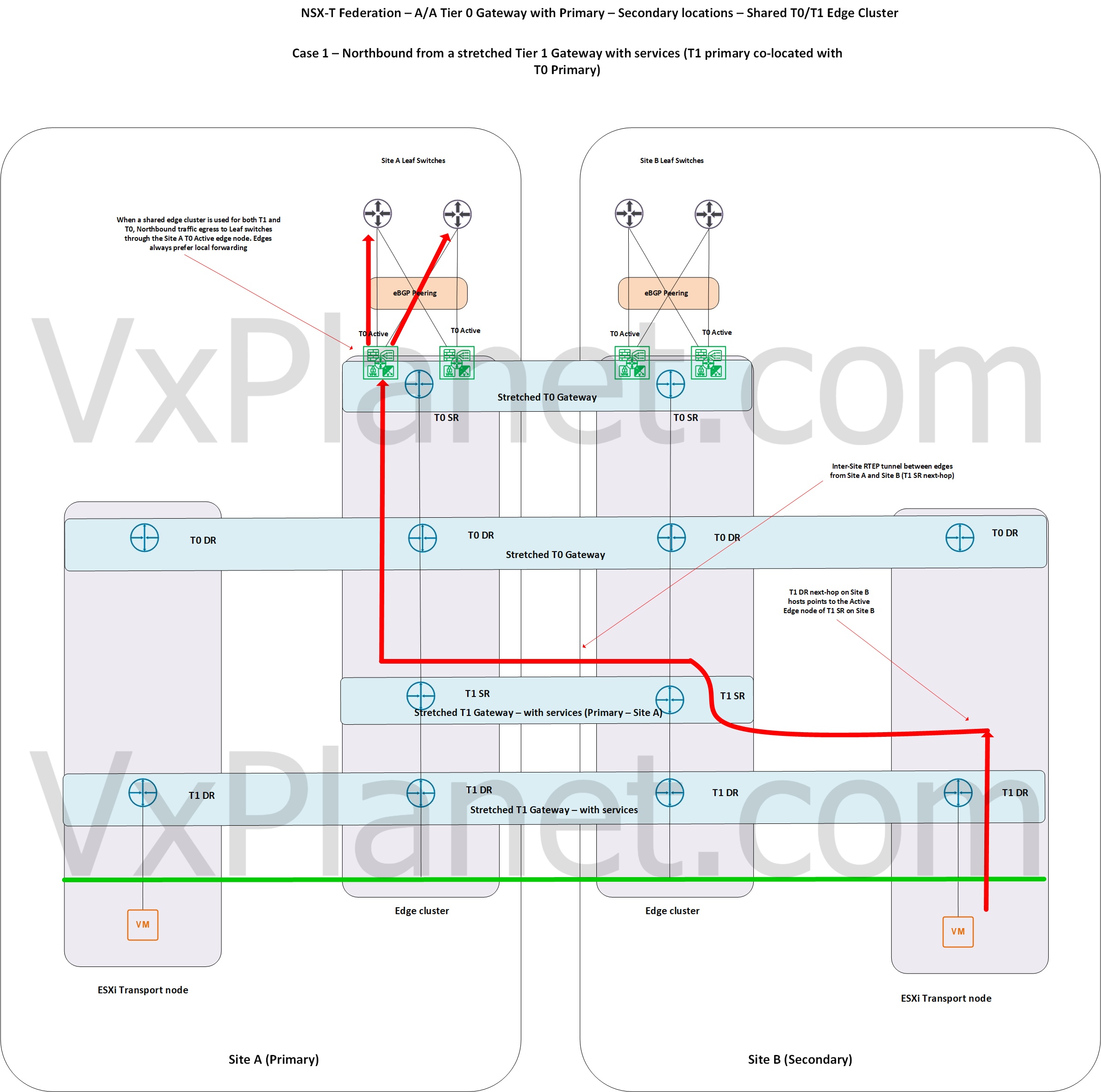
Case 1 – Northbound from a stretched T1 gateway with SR on a shared T0/T1 edge cluster attached to stretched A/A T0 Gateway
The below sketch shows a northbound traffic from a logical segment on secondary location that is attached to a stretched T1 gateway with SR primary on Site A. Notice that traffic crossed to Ste A to complete the T1 SR lookup and thereafter all northbound lookup happened locally. In this shared edge cluster design, only the edge node hosting the T1 SR active construct is involved in northbound routing and as such, we have minimal ECMP paths northbound.
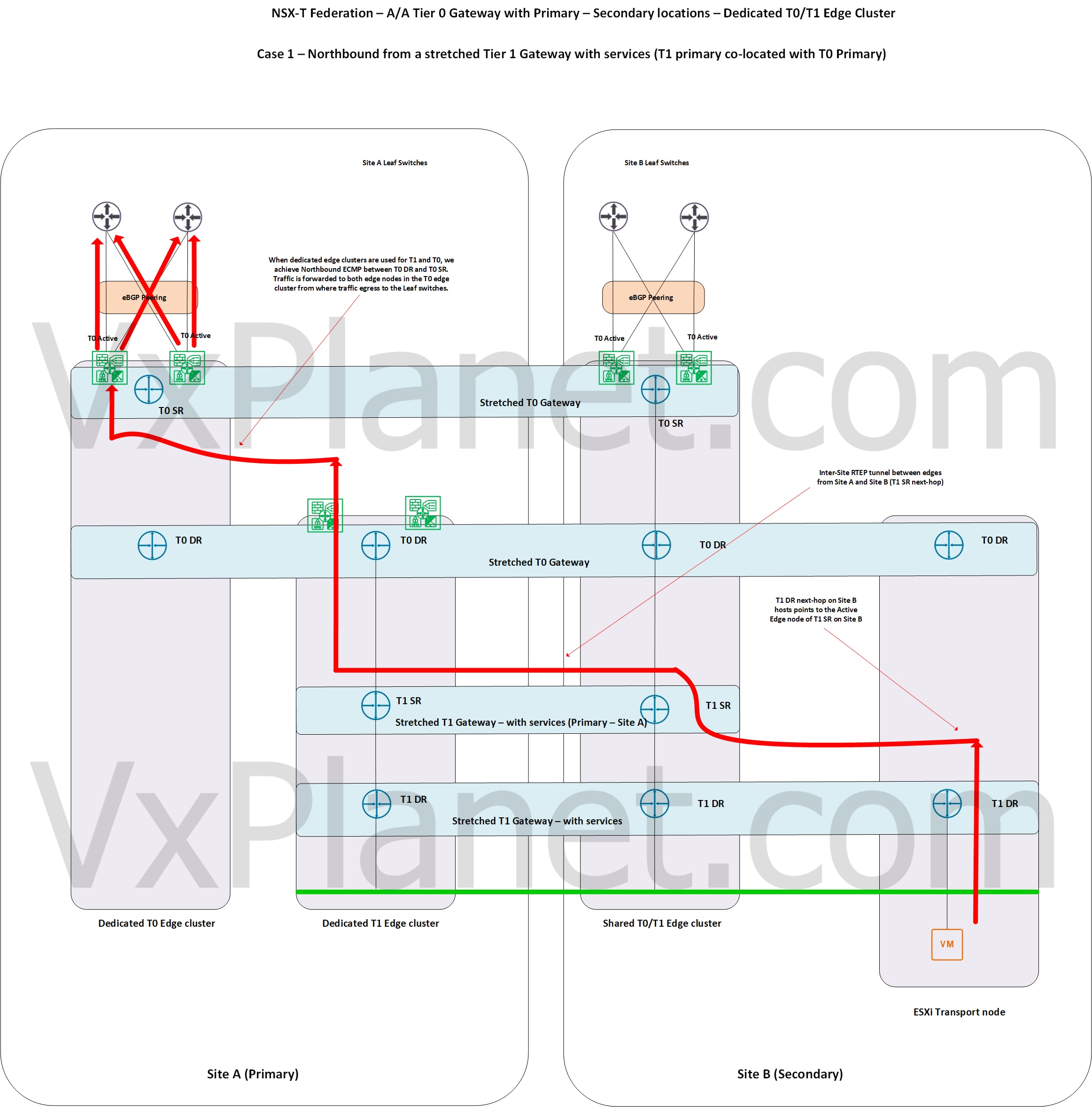
Case 2 – Northbound from a stretched T1 gateway with SR on a dedicated T0/T1 edge cluster attached to stretched A/A T0 Gateway
In the below sketch, we have introduced a dedicated edge cluster for T1 gateway in Site A. After the T0 DR lookup on the edges in Site A, traffic has tunnelled to the T0 edge cluster for T0 SR lookup from where it is egressed to the ToR networks. This design leverages T0 DR to T0 SR ECMP from the T1 edge cluster to the T0 edge cluster, which gives more paths northbound.
Let’s look at the routing configs on T1 SR constructs on both locations to get more clarity.
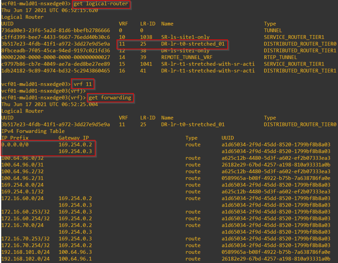
This is the forwarding table from the T1 SR active edge node on Site B (secondary). The next-hop points to the T1 SR active edge node on Site A (T1 primary).

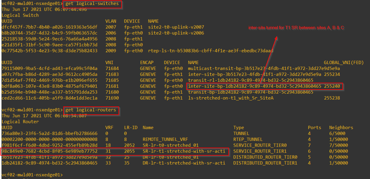
This is the tunnel interface of the T1 SR active edge node on Site B. This is on the inter-site geneve tunnel that spans across all the locations to which the T1 gateway has a span. Note that T1 SR next-hop reachability is achieved over this tunnel.
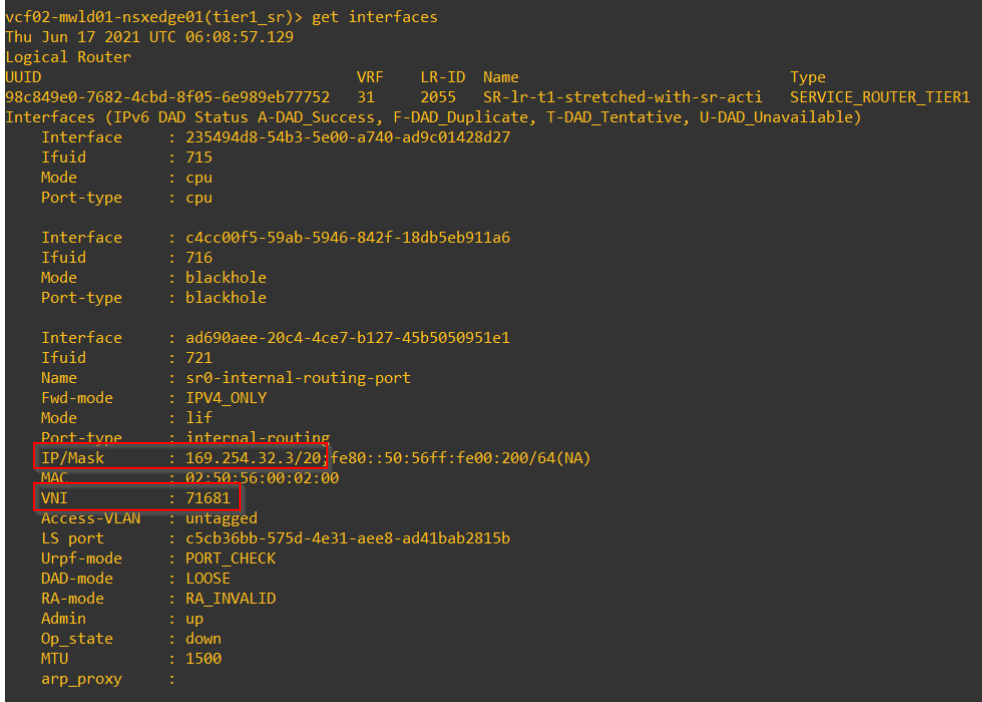
Below is the tunnel interface on the active T1 SR edge node on Site A (which is the next-hop the secondary locations are pointing to)
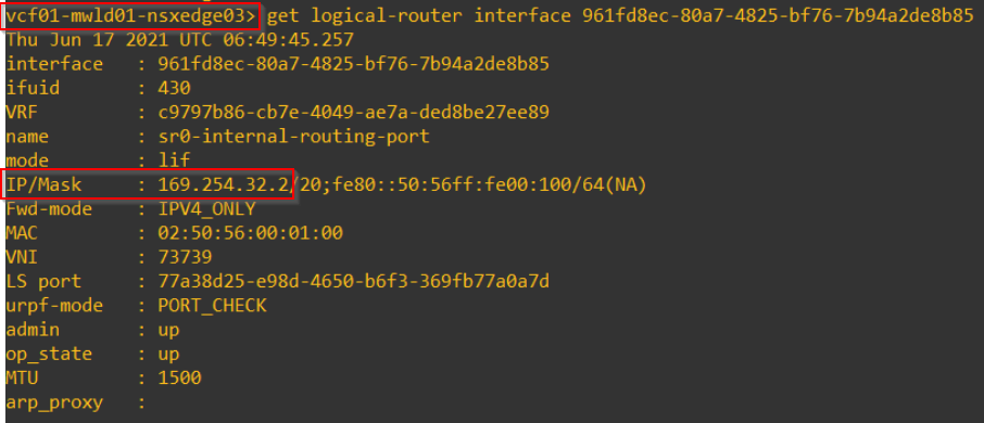
and we have ECMP from T0 DR on the T1 edge cluster to the T0 SR construct on the T0 edge cluster northbound.
Attaching logical segment and control plane – VTEP Groups, L2forwarders and RTEP groups
Now let’s attach a logical segment downstream to this stretched T1 gateway. As discussed in the previous article (Part 9 – Federation Control plane), VTEP group for the stretched logical segment will choose the same edge pair that hosts the SR construct of the stretched T1 gateway. As such edge03 and edge04 will be the edge pairs chosen.
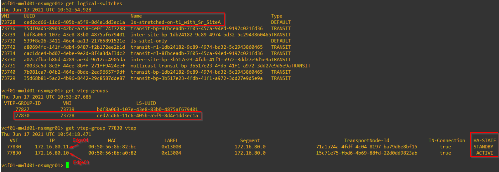
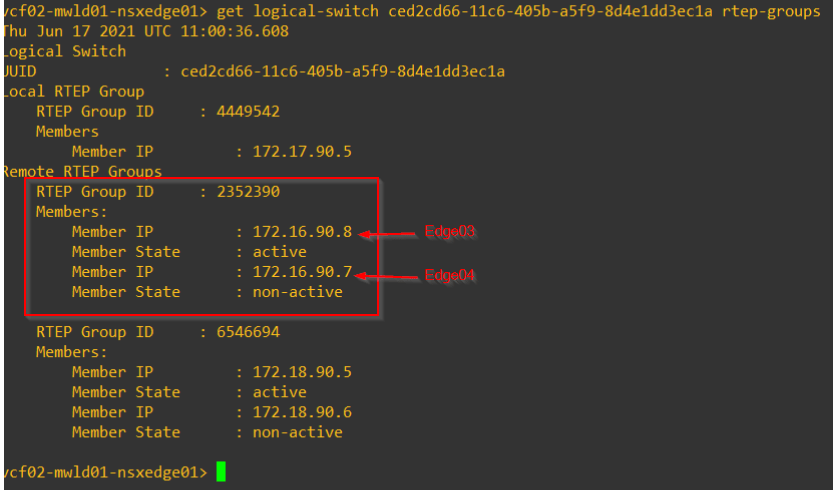
L2forwarder edge pair and HA mode is reflected from the VTEP groups and RTEP groups, and as such edge03 is the active L2forwarder.

Let’s wrap up and move on to the final part of the series – Network Recovery. Stay tuned!!!
I hope the article was informative.
Thanks for reading.
Continue reading? Here are the other parts of this series:
Part 1 : https://vxplanet.com/2021/04/13/nsx-t-federation-part-1-onboarding/
Part 8 : https://vxplanet.com/2021/06/02/nsx-t-federation-part-8-tier-1-gateway-placement-considerations/
Part 9 : https://vxplanet.com/2021/06/09/nsx-t-federation-part-9-federation-control-plane-explained/
Part 11 : https://vxplanet.com/2021/06/20/nsx-t-federation-part-11-site-failures-and-network-recovery/
