

Welcome to Part 9 of the blog series on NSX-T Federation where we will discuss about the Federation Control Plane.
In a non-federated NSX-T infrastructure (single site or multi-site), we mostly deal with three control plane tables for networking – MAC table, ARP table and VTEP table. In federation we have four additional tables – VTEP-Groups table, RTEP-groups table, L2forwarders and global VNI table. Let’s take a closer look at each of them, but before that let’s take a note of the key concepts in L2 stretching:
- In NSX-T Federation, ESXi transport nodes in one location won’t establish TEP connectivity with other ESXi transport nodes in other locations. This reduces the number of inter-site tunnels when compared to a traditional NSX-T multisite solution.
- All inter-site communication happens via the edge nodes only. To be more specific, for each stretched logical segment, there is an Edge-RTEP group which takes care of L2 forwarding between sites (inter-site). RTEPs are the entry and exit points to/from a location. Currently only one RTEP interface is supported per edge node.
- Local TEP tunnels terminates at the edge nodes of each location. TEP tunnels won’t span to other locations. VNIs for TEP tunnels are called local VNIs. More specifically, for each stretched L2 segment, there is an Edge-VTEP-Group to where the local ESXi transport nodes forwards the L2 traffic for other locations.
- For each stretched L2 segment, there is an inter-site tunnel (Global VNI) established between the RTEP groups across locations. L2forwarder edges glues the local TEP VNI with the Global VNI for L2 stretchability across locations.
- With this architecture, we have a more deterministic traffic pattern for inter-site communication.
- We are not pooling all the locations together and hence not dealing with a tunnel-everywhere scenario.
- Esxi transport nodes don’t have visibility to the rtep-groups in other locations. Remote mac addresses in the mac-address table points to it’s local VTEP-group only.
- Global manager doesn’t maintain control plane information. Control plane is synced between the local managers of all the locations.
- Local VNIs are assigned by the local managers in each location. Global VNIs are assigned by the Global manager. Local VNIs are only locally significant. As such for a stretched segment, it can have different local VNIs across locations.
- VTEP-groups are meant for Local VNI and RTEP-groups are meant for global VNI.
- Both VTEP-groups and RTEP-Groups can have only 2 member edge nodes.
Let’s get started:
Current Environment
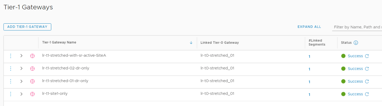
We will use the same topology used in Part 4 & Part 5 which is a stretched Active-Active T0 Gateway with location Primary-Secondary. We have three locations – Site A, B & C with four T1 gateways attached downstream.
- lr-t1-stretched-01-dr-only – T1 gateway – DR only spans to all three locations
- lr-t1-stretched-02-dr-only – T1 gateway – DR only spans to all three locations
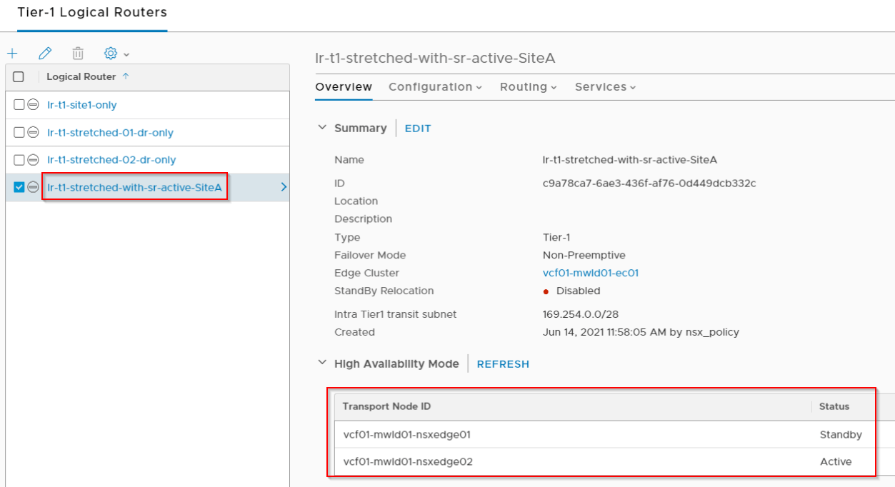
- lr-t1-stretched-with-sr-active-SiteA – T1 with SR that spans to all locations with T1 primary on Site A
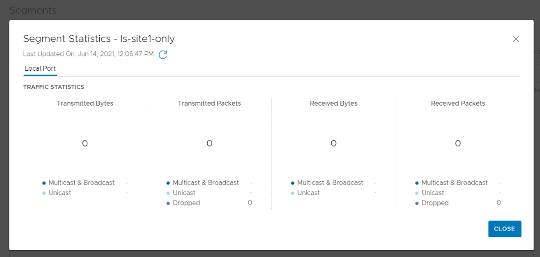
- lr-t1-site1-only – Non-stretched T1 that spans to Site A only.
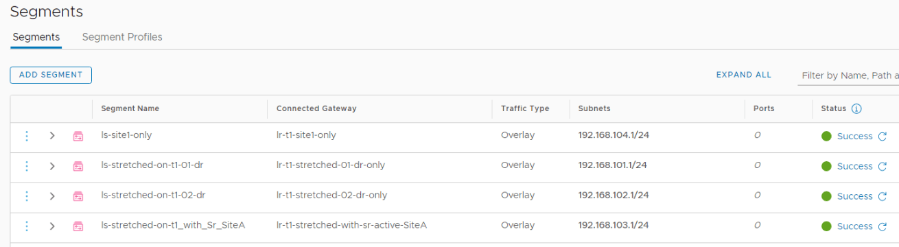
We also have segments attached to respective T1 gateways.
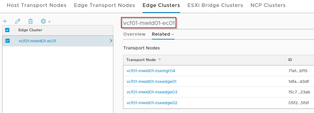
We added two more edge nodes to the edge cluster in Site A to make it a total of 4.
VTEP-Groups
VTEP groups are a pair of edge nodes in the edge cluster responsible for terminating the TEP VNI for a stretched segment from the ESXi transport nodes within a location. Each stretched segment will have a VTEP group with Active-Standby edge node members. The active edge node is the actual forwarder for that location. Selection of edge nodes of a VTEP-group depends on the upstream gateway to which the logical segment is attached to:
- A DR only T1 gateway will choose the VTEP member pairs from the T0 edge cluster to which it is attached. Multiple DR-only T1 gateways can either share the edge pair or choose a new edge pair if the T0 edge cluster has atleast 4 members. All segments on a DR-only T1 gateway will share the same edge pair for the VTEP-groups
- A T1 gateway with SR will always choose the edge pair hosting it’s SR construct. Whether it is a shared T0-T1 edge cluster or a dedicated T1 edge cluster with more than 2 edge nodes, only this edge pair will be chosen for the VTEP-groups of all the segments attached to the T1 gateway.
- Similarly segments attached directly to T0 A/S gateway will always choose the edge pair hosting the T0 SR construct for the VTEP-groups.
- Segments attached directly to T0 A/A gateway will choose the edge pairs from the T0 edge cluster. Segments can either share the edge pair or choose a new edge pair if the T0 edge cluster has atleast 4 members.
The below sketch depicts the VTEP groups for four stretched segments, two attached to GREEN T1 gateway and two attached to RED T1 gateway, both with DR only.
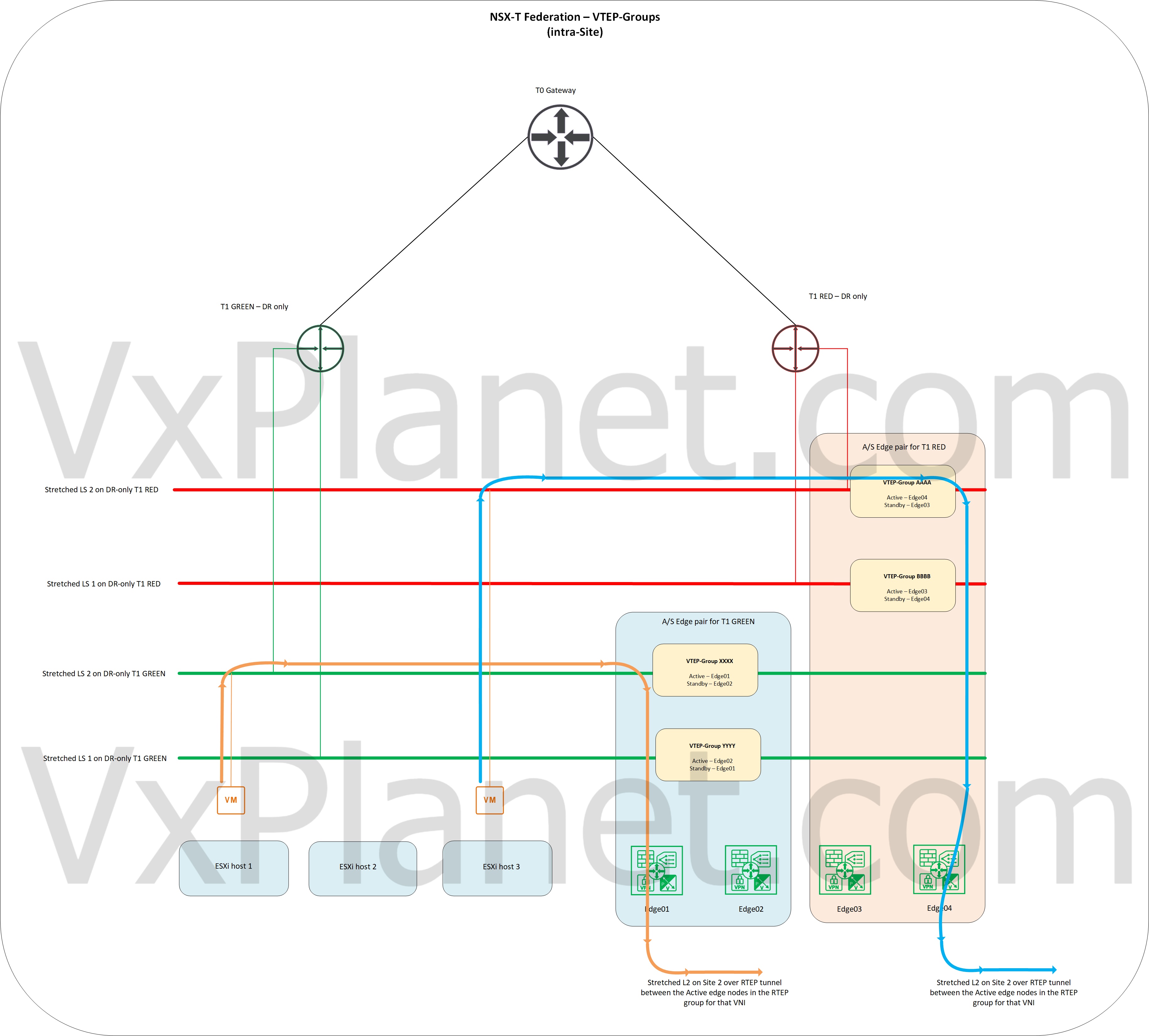
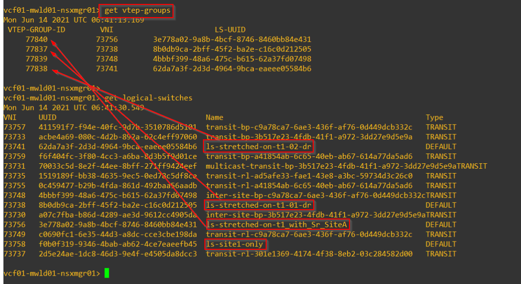
As discussed earlier, each stretched logical segment (local VNI) will have a vtep-group. Non-stretched segments won’t have a VTEP group. Below outputs are from Site A.
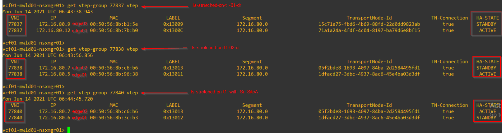
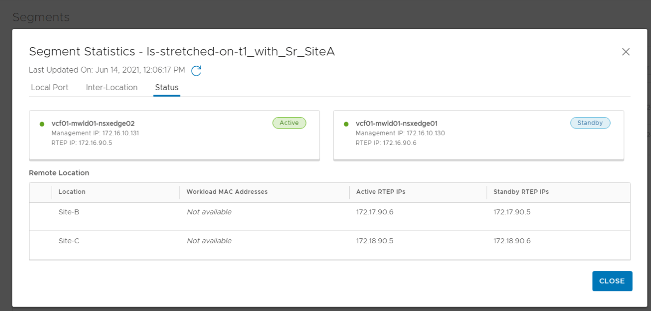
Since we had 4 edge nodes in the Site A edge cluster, each DR-only T1 gateway chose different edge pairs for VTEP-groups. T1 Gateway with SR chose the edge pair hosting it’s SR construct for the VTEP-groups.
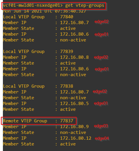
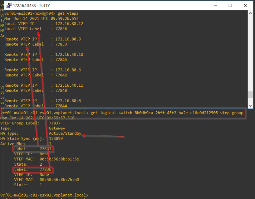
VTEP-group table on the edges lists all the VTEP-groups, both local and remote.
Just FYI, below is the VTEP-table from an ESXi transport node. The group members are listed using VTEP labels which can be identified from the edge nodes.
RTEP-Groups
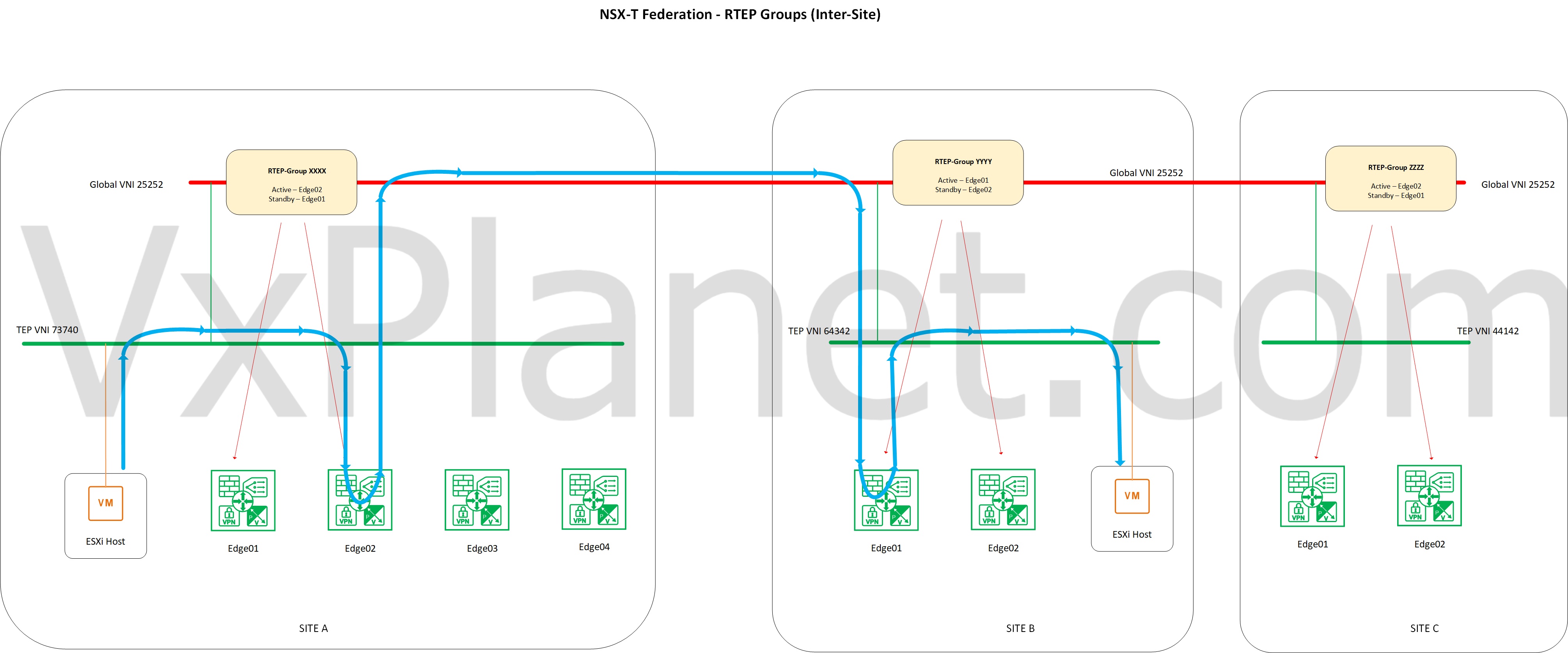
RTEP groups are a pair of edge nodes in the edge cluster responsible for stretching the L2 segments over the global VNI. Each stretched segment will have an RTEP group with Active-Standby edge node members. The active member is responsible for establishing the geneve tunnel with the active RTEP group member in other locations over the global VNI for L2 stretchability. RTEP-group edge pair follows the VTEP-Group edge pair for the specific stretched segment.
RTEP-groups are transparent to the ESXi transport nodes, they only see the VTEP-groups. The below sketch depicts this.
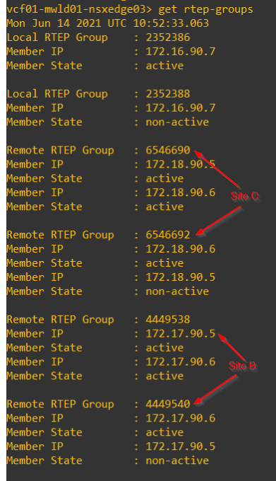
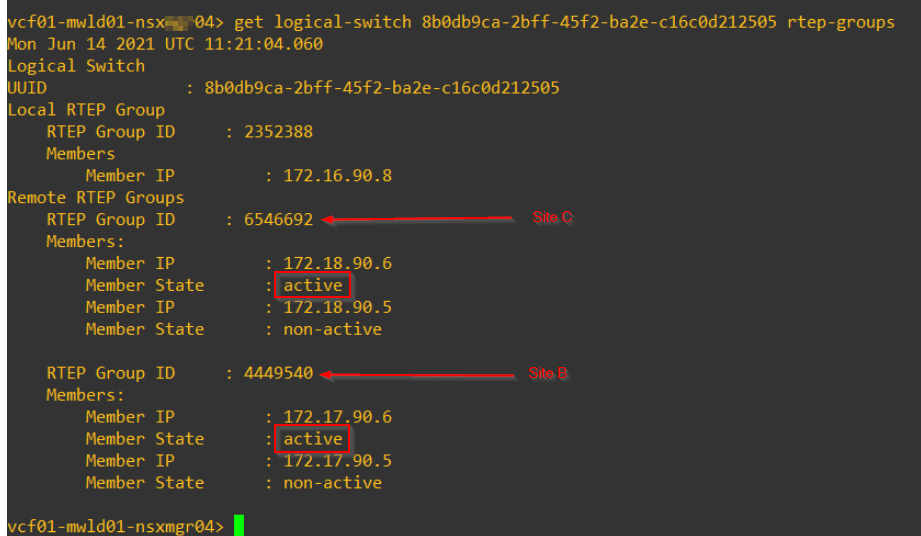
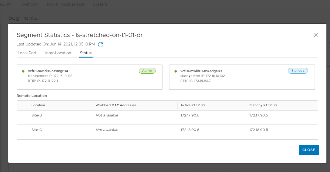
Below is the RTEP-Group table for a stretched logical segment attached to DR-only T1 gateway.
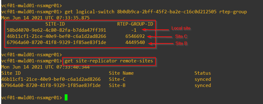
Like the VTEP group table, edge node displays both local as well as remote RTEP tables. VNI specific RTEP-group table will be available only on the respective RTEP-group members.
L2Forwarders
L2Forwarder is an edge construct that does the transition of local TEP VNI to the global VNI. It is also deployed in an edge pair in Active-Standby form and follows the same edge pair and HA state of the VTEP and RTEP groups for the specific stretched segment.
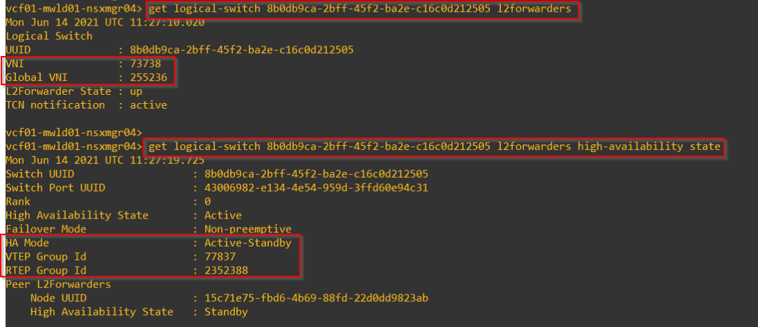
For the logical segments that we created earlier, below is the L2forwarder status from the console. Note that the edge pair and HA status is reflected from the VTEP and RTEP groups.

Non-stretched segments will not have VTEP-Group, L2Forwarder and RTEP-group.
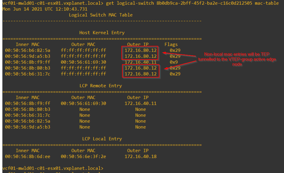
Mac-address Table
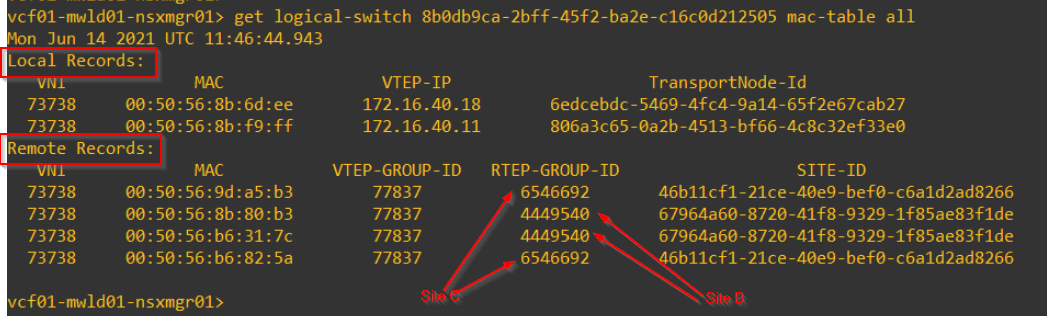
In Federation, mac-address-table on each location will also have a field for ‘Remote Records’.
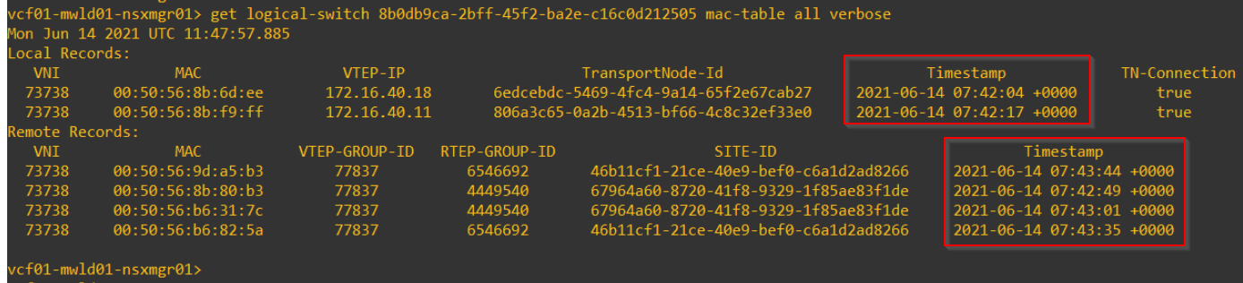
mac-table also has a timestamp (seen in verbose output) to handle mac-address conflicts. A typical scenario is where VMs are recovered in Site 2 where Site 1 hasn’t completely flushed the older mac entries.
Remote mac-addresses in the mac-address table of edge nodes for a specific stretched segment will be behind the RTEP group.
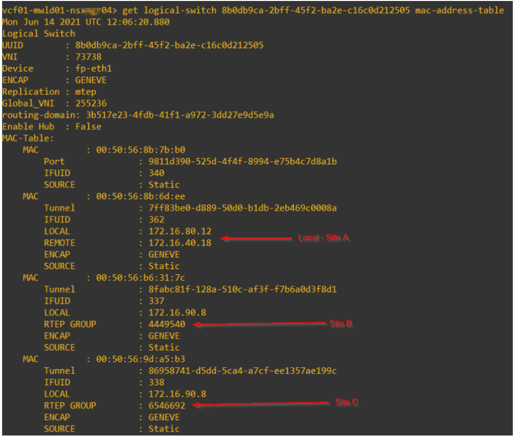
Remote mac-addresses in the mac-address table of ESXi transport nodes for a specific stretched segment will be behind the VTEP group.
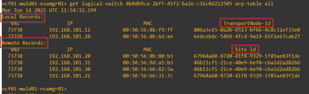
ARP Table
Similar to mac table, ARP table will also have both ‘Local’ and ‘Remote’ records.
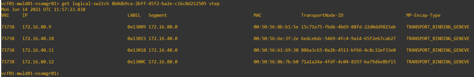
VTEP Table
VTEP table for a stretched segment in a location will display only it’s local members – ESXi transport nodes and the VTEP-Group edge members.
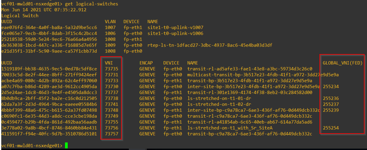
Global VNI Table
All stretched segments will have a global VNI assigned by the global manager. Non-stretched segments wont have one.
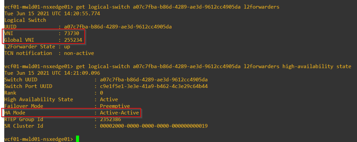
Active-Active L2Forwarders
Presently, only Active-Standby HA mode is supported for L2forwarders for the stretched segments. However for the inter-site transit logical segment (internal), we do have an Active-Active mode available. This inter-site transit segment is used by the T0 SR constructs in locations for the inter-site iBGP peering (inter-SR routing) and to next-hop to the other location for northbound reachability. This Active-Active mode also helps to achieve ECMP for the inter-site tunneled traffic.
Below is the inter-site transit segment for the T0 SR and it’s RTEP groups.
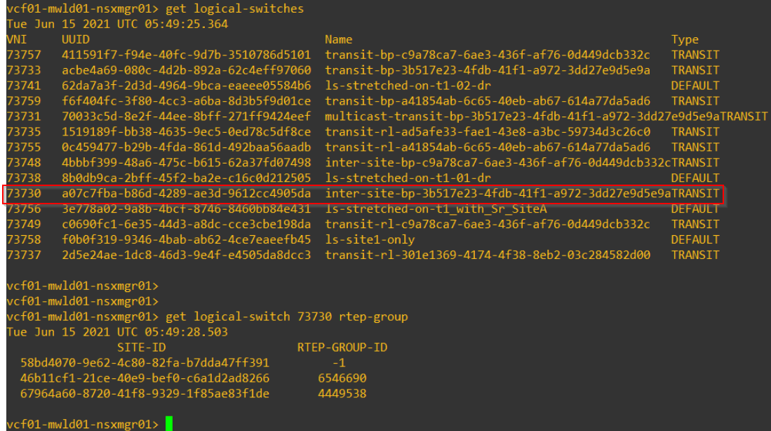
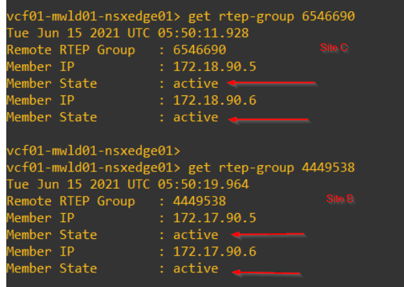
and the state of RTEP groups in other locations.
As discussed earlier, the L2forwarder HA state is reflected from the RTEP group
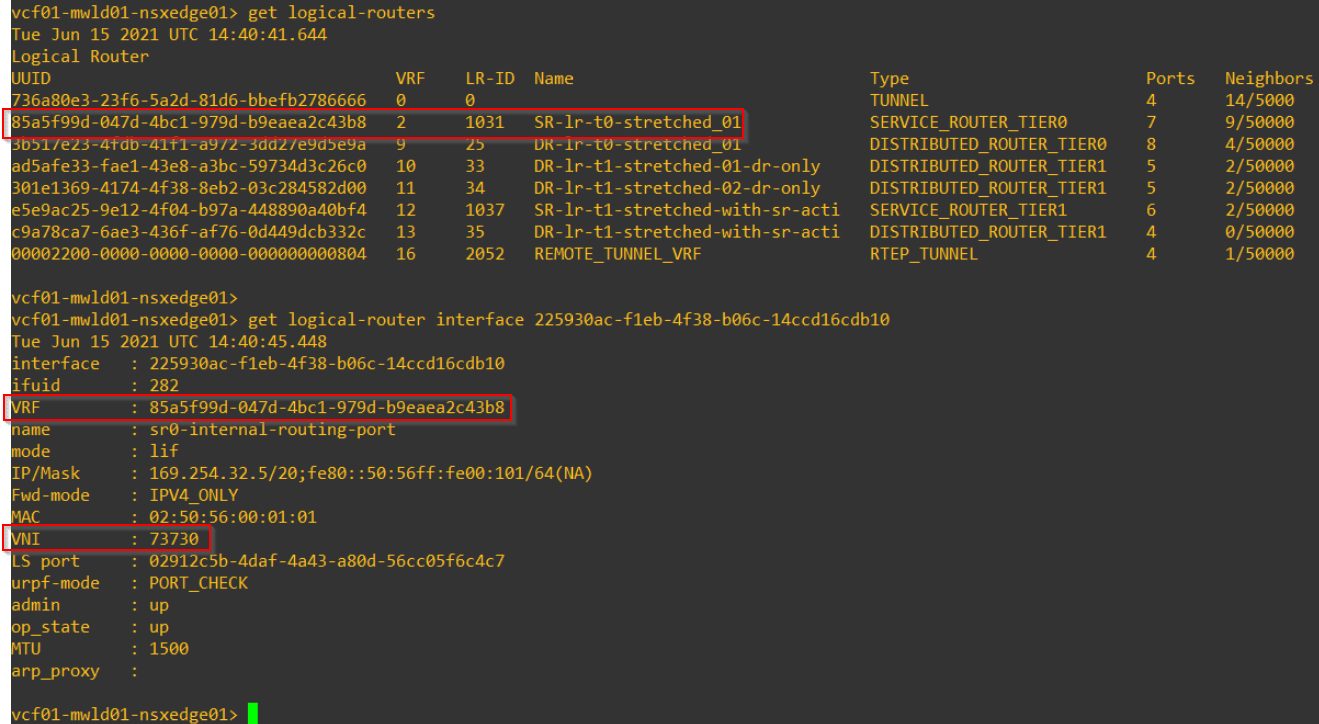
This is the tunnel interface on the T0 SR (on the same VNI) for iBGP peering and for next-hop to other locations.
Time to wrap up!!!
We are not done with Federation yet, have two more to go. We will meet in the next article to discuss on dedicated Tier 1 edge clusters in NSX-T Federation.
I hope the article was informative.
Thanks for reading.
Continue reading? Here are the other parts of this series:
Part 1 : https://vxplanet.com/2021/04/13/nsx-t-federation-part-1-onboarding/
Part 8 : https://vxplanet.com/2021/06/02/nsx-t-federation-part-8-tier-1-gateway-placement-considerations/
Part 11 : https://vxplanet.com/2021/06/20/nsx-t-federation-part-11-site-failures-and-network-recovery/
