

Now that we covered Part 6 where we discussed about the configuration and routing of stretched Active-Active Tier 0 Gateway with location All-Primary, let’s do a packet walk to understand the North-South and East-West traffic flow in more detail. If you missed Part 6, you can read it here:
In Part 6, we discussed that, for a stretched Active-Active T0 Gateway with location All-Primary,
- All locations advertise and learn prefixes from the Leaf switches over the BGP relationship.
- Each location advertises only it’s local prefixes. Unlike Primary-Secondary topologies, remote prefixes are not advertised from any primary location.
- Prefixes learned over the default vrf have higher preference over the ones learnt through the inter-sr vrf. Default vrf learned routes are locally learned from the Leaf switches (via eBGP) and are placed in the forwarding table with next hop pointing to the leaf switches. This way each location has local egress.
- To reach customer networks local to a specific location (location specific prefixes), edges from other locations will next-hop to the edges in the specific location for egress.
- Ingress need to be controlled outside of NSX-T federation.
- Local egress capability is influenced by the placement of primary location of a stretched T1 gateway with services.
Let’s get started.
Northbound from a segment attached to stretched Tier 1 Gateway with no services (DR only)
- For a northbound flow from a segment attached to the stretched Tier 1 Gateway (DR only), the T1 DR lookup happens locally on the ESXi transport node.
- T0 DR lookup also happens locally on the ESXi transport node.
- For the T0 SR lookup, traffic will be tunnelled (using TEP interfaces) to one of the Active Edge nodes in the same location (T0 DR to SR ECMP) from where it will egress out over it’s two T0 uplinks.
- Remember that from the ESXi transport nodes to the edges, we have Tier 0 DR to SR ECMP northbound. This ECMP is scalable.
The below sketch depicts the flow from Site A & B:

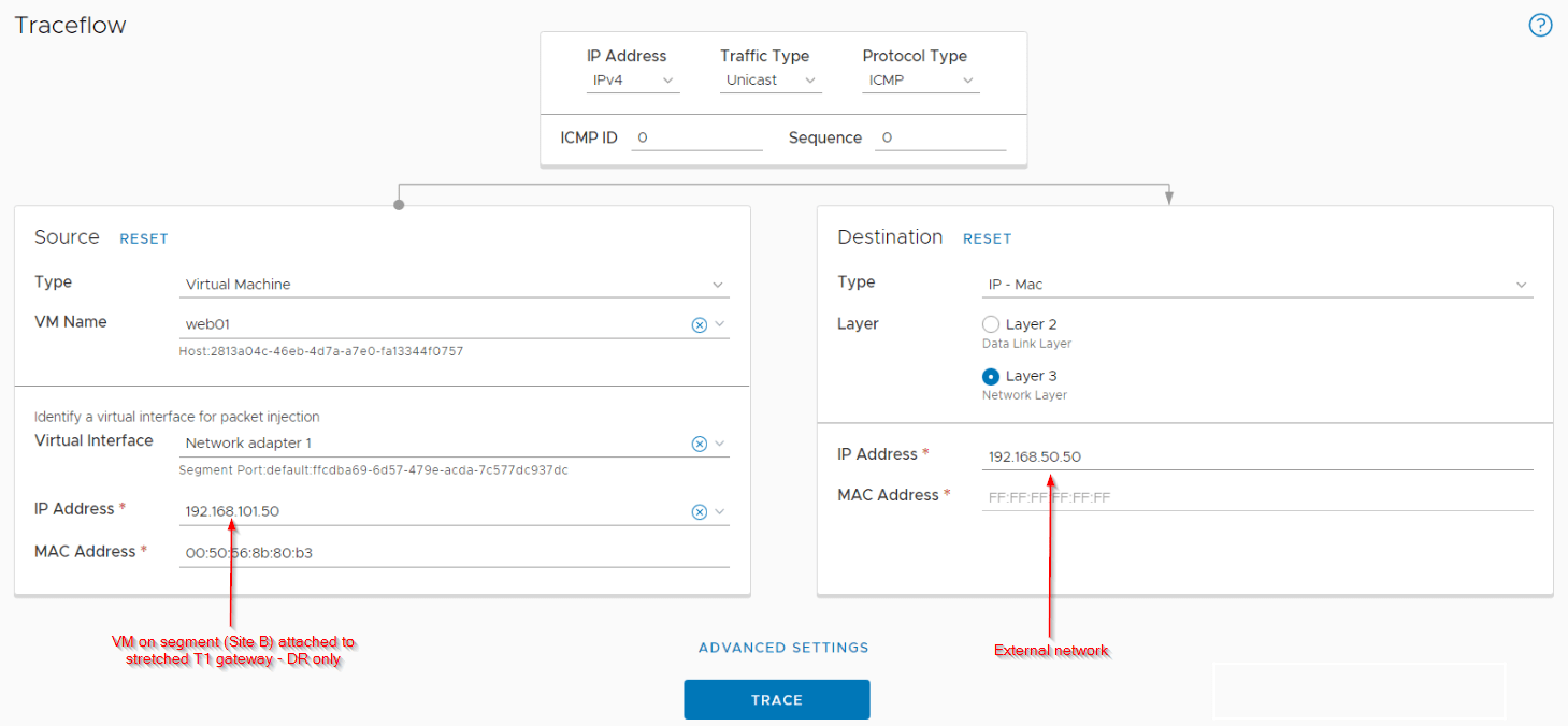
Let’s do a traceflow from Site B northbound to confirm the flow:
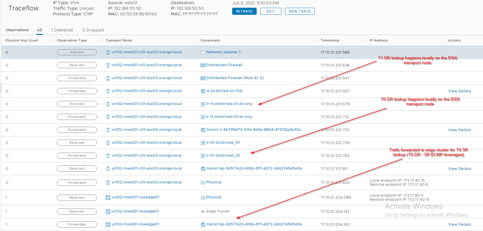
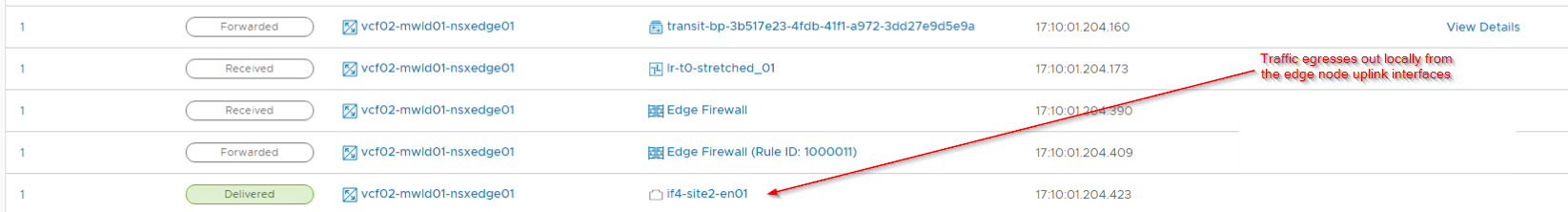
Notice that traffic has egressed locally (from Site B) to the Leaf switches.
Northbound from a segment attached to stretched Tier 1 Gateway in Site B with T1 SR on Site A as Primary location
- For a northbound flow from a segment attached to the stretched Tier 1 Gateway in Site B, the T1 DR lookup happens locally on the ESXi transport node.
- To reach T1 SR , traffic is tunnelled (TEP interfaces) to the Active edge node (for T1) in the same location, Site B
- Since the T1 SR primary location is Site A, traffic will be RTEP tunnelled to Site A’s active edge node for T1 SR.
- T0 DR lookup happens locally on Site A’s active edge node (for T1 SR).
- T0 SR lookup also happens locally on the same edge node in Site A and will egress out over it’s two T0 uplink interfaces. Note that only one edge node (the active node of T1) is involved in northbound routing in this case.

Northbound from a segment attached to stretched Tier 1 Gateway in Site B with Site B itself as the T1 SR Primary location
- For a northbound flow from a segment attached to the stretched Tier 1 Gateway with SR construct in Site B, the T1 DR lookup happens locally on the ESXi transport node.
- To reach T1 SR , traffic is tunnelled (TEP interfaces) to the Active edge node (for T1) of Site B.
- T0 DR lookup happens locally on the edge node in Site B itself.
- T0 SR lookup also happens locally on the edge node and will egress out over it’s two T0 uplink interfaces. Note that only one edge node (the active node of T1) is involved in northbound routing in this case as well.

Northbound from a segment attached to non-stretched Tier 1 Gateway with services (with SR)
- For a northbound flow from a segment attached to the non-stretched Tier 1 Gateway with SR construct in Site B, the T1 DR lookup happens locally on the ESXi transport node.
- To reach T1 SR , traffic is tunnelled (TEP interfaces) to the Active edge node (for T1) of Site B.
- T0 DR lookup happens locally on the edge node in Site B itself.
- T0 SR lookup also happens locally on the edge node and will egress out over it’s two T0 uplink interfaces. Note that only one edge node (the active node of T1) is involved in northbound routing.

Northbound from Site A to Site B specific customer networks
Customer prefixes that are local to Site B will be advertised to all other locations through the inter-SR iBGP. Even though these prefixes are received with a lower local preference of 90, they dont exist in the default vrf table of other locations. As such, these prefixes from inter-SR table will be placed into the forwarding table with next-hop pointed to Site B for egress.

East-West between a stretched T1 Gateway with and without services
The traffic patterns for east-west flows are the same as previous Primary – Secondary topologies which we discussed in Parts 2 to 5. This is because T0 SR construct is not involved in East-West routing.
The below sketch shows an East-West communication between two VMs on the same ESXi transport node in Site B – one attached to a stretched T1 Gateway with SR on Site A as primary and the other attached to a stretched T1 Gateway with DR-only.

Notice that traffic had to cross to Site A to complete the T1 SR lookup.
East-West between a non-stretched T1 Gateway with services and a stretched T1 Gateway with services
The below sketch shows an East-West communication between two VMs on the same ESXi transport node in Site B – one attached to a non-stretched T1 Gateway with SR and the other attached to a stretched T1 Gateway with SR on Site A as primary.

Time to wrap up!!!
With this we have covered all the stretched Tier 0 topologies, North-South & East-West routing and their packet walks. I hope these articles complement your NSX-T federation learning to help in deciding the correct T0 / T1 placements and make effective design choices for multisite.
We will meet in the next article to discuss on T1 SR placements and it’s effect on multisite routing. Stay tuned.
Thanks for reading
Continue reading? Here are the other parts of this series:
Part 1 : https://vxplanet.com/2021/04/13/nsx-t-federation-part-1-onboarding/
Part 8 : https://vxplanet.com/2021/06/02/nsx-t-federation-part-8-tier-1-gateway-placement-considerations/
Part 9 : https://vxplanet.com/2021/06/09/nsx-t-federation-part-9-federation-control-plane-explained/
Part 11 : https://vxplanet.com/2021/06/20/nsx-t-federation-part-11-site-failures-and-network-recovery/

This iis a great post thanks
Thanks Victor