

Welcome to the final and Part 11 of the blog series on NSX-T Federation. In this article, we will take a look at site failure scenarios, Global manager Active/Standby switchover, site switchover and stretched network recovery with three different Tier 0 Gateway topologies.
I have given links to the previous ten parts of this Federation series towards the end of this article, please go through if you weren’t already following along. Let’s get started:
Current environment
Like all the previous articles, we have three locations – Site A, B and C with three different Tier 0 Gateway topologies:
- Stretched Active-Active Tier 0 Gateway with location Primary-Secondary
- Stretched Active-Active Tier 0 Gateway with location All-Primary
- Stretched Active-Standby Tier 0 Gateway with location Primary-Secondary
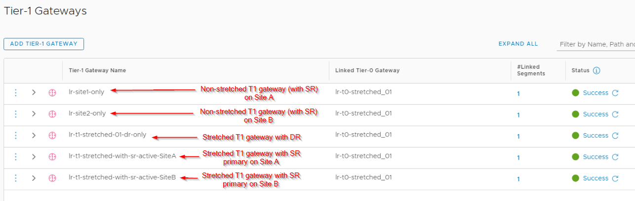
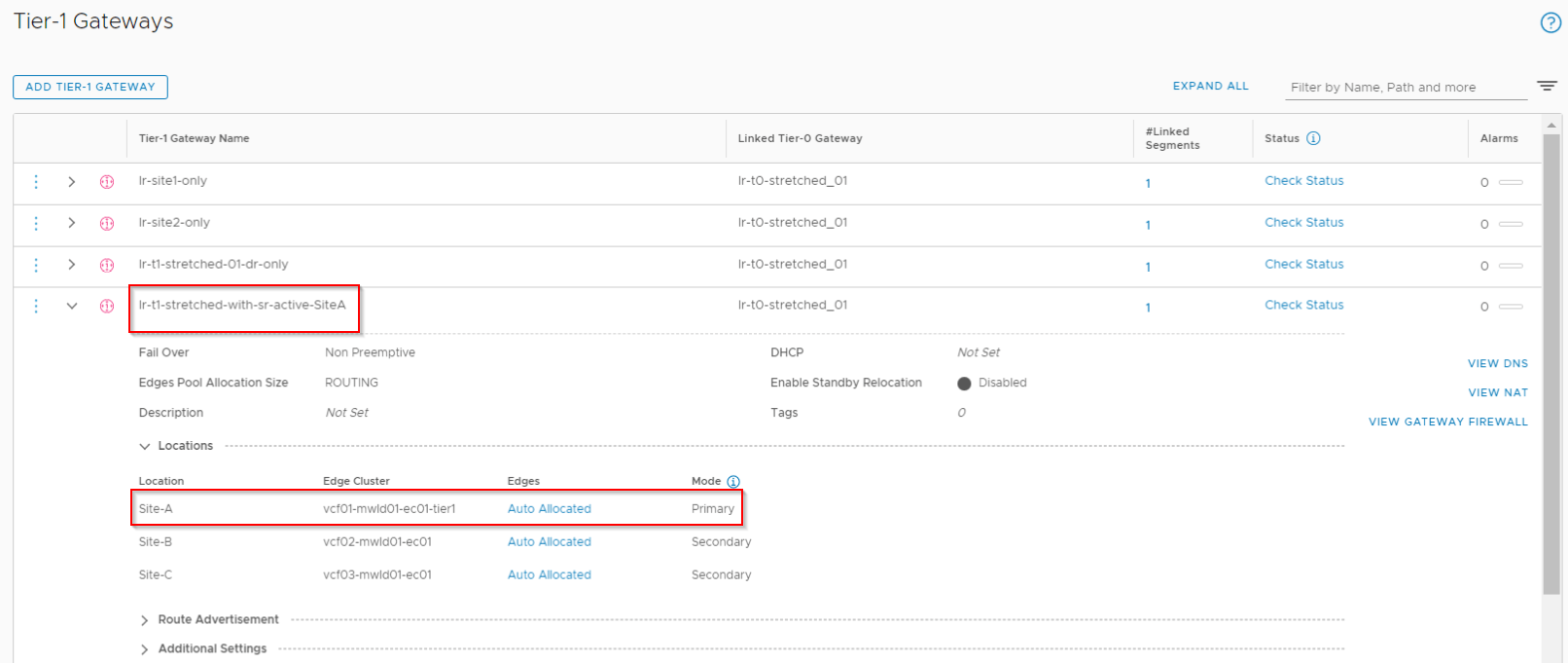
For each Tier 0 gateway topology, we have 5 Tier 1 gateways attached downstream:
- Non-stretched Tier 1 gateway on Site A (lr-site1-only)
- Non-stretched Tier 1 gateway on Site B (lr-site2-only)
- Stretched Tier 1 Gateway – DR only with span across all locations (lr-t1-stretched-01-dr-only)
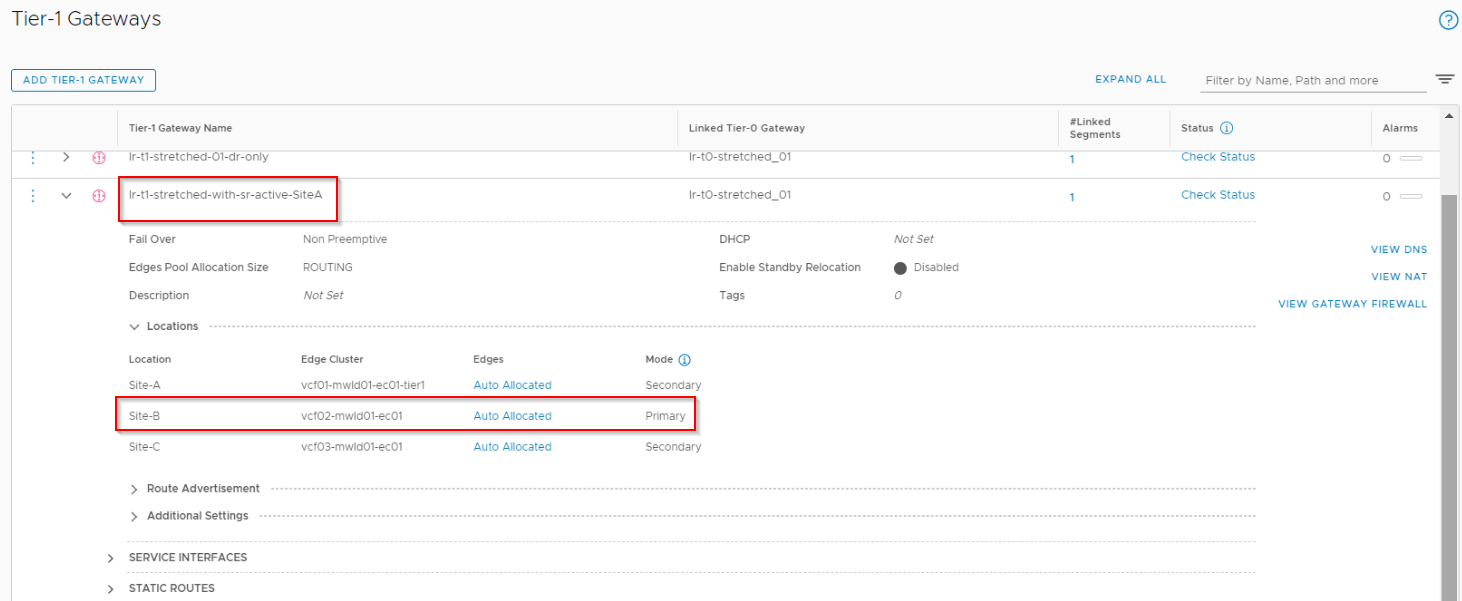
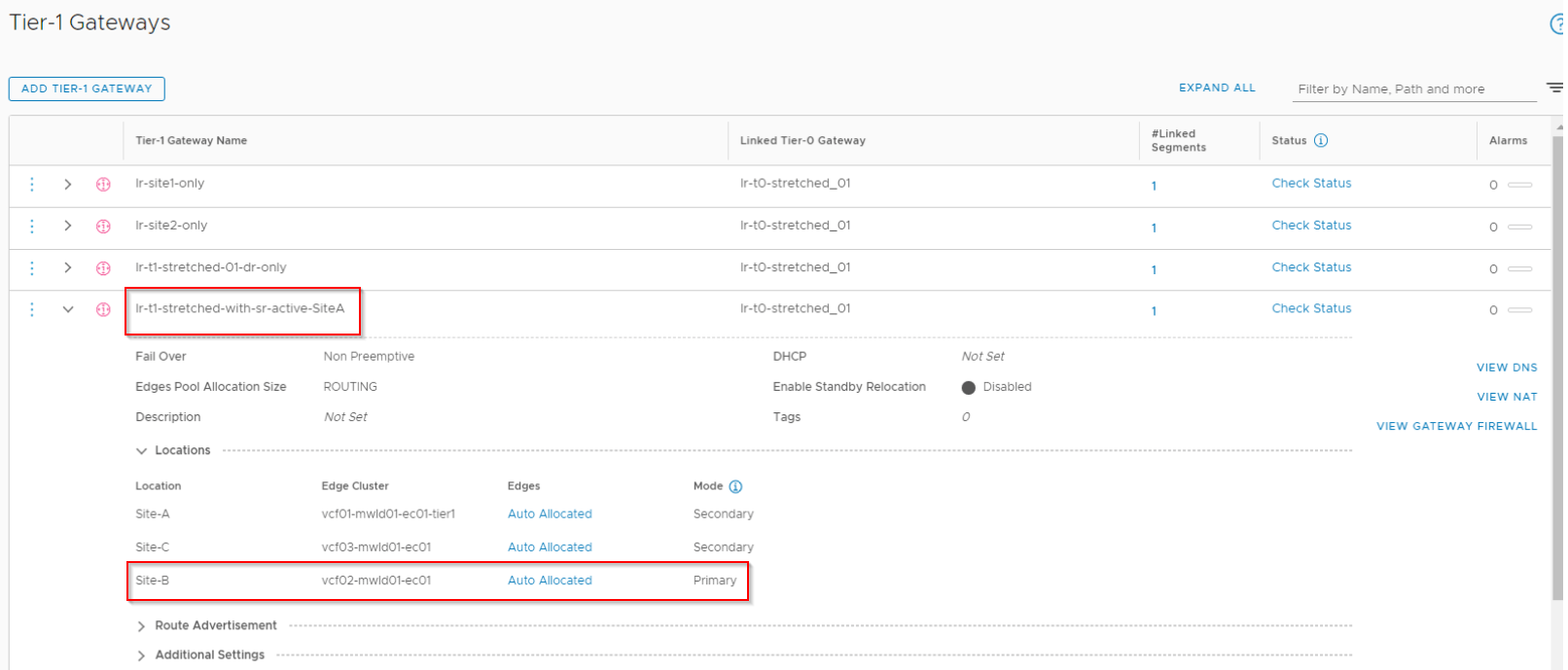
- Stretched Tier 1 Gateway with SR primary on Site A (co-located with T0 primary) with span across all locations (lr-t1-stretched-with-sr-active-siteA)
- Stretched Tier 1 Gateway with SR primary on Site B (not co-located with T0 primary) with span across all locations (lr-t1-stretched-with-sr-active-siteB)
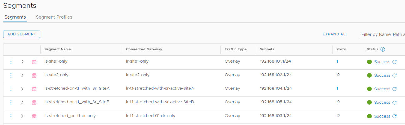
We also have a logical segment attached to each Tier 1 gateway. The span of this logical segment is equal to the span of it’s upstream T1 gateway.
- ls-site1-only
- ls-site2-only
- ls-stretched-on-t1-dr-only
- ls-stretched-on-t1-with-sr-active-siteA
- ls-stretched-on-t1-with-sr-active-siteB
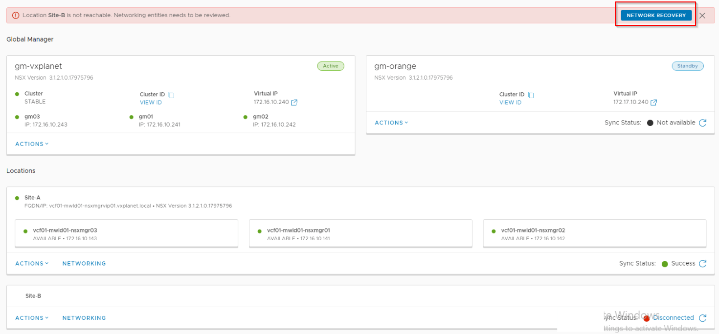
The GM Active cluster is hosted in Site A and GM standby cluster is hosted in Site B.
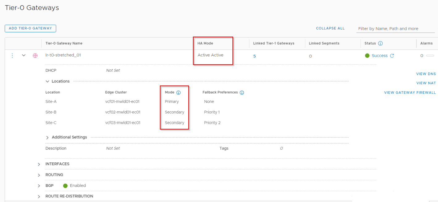
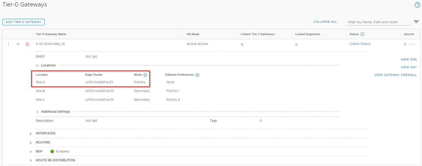
Stretched Active-Active Tier 0 Gateway with location Primary-Secondary
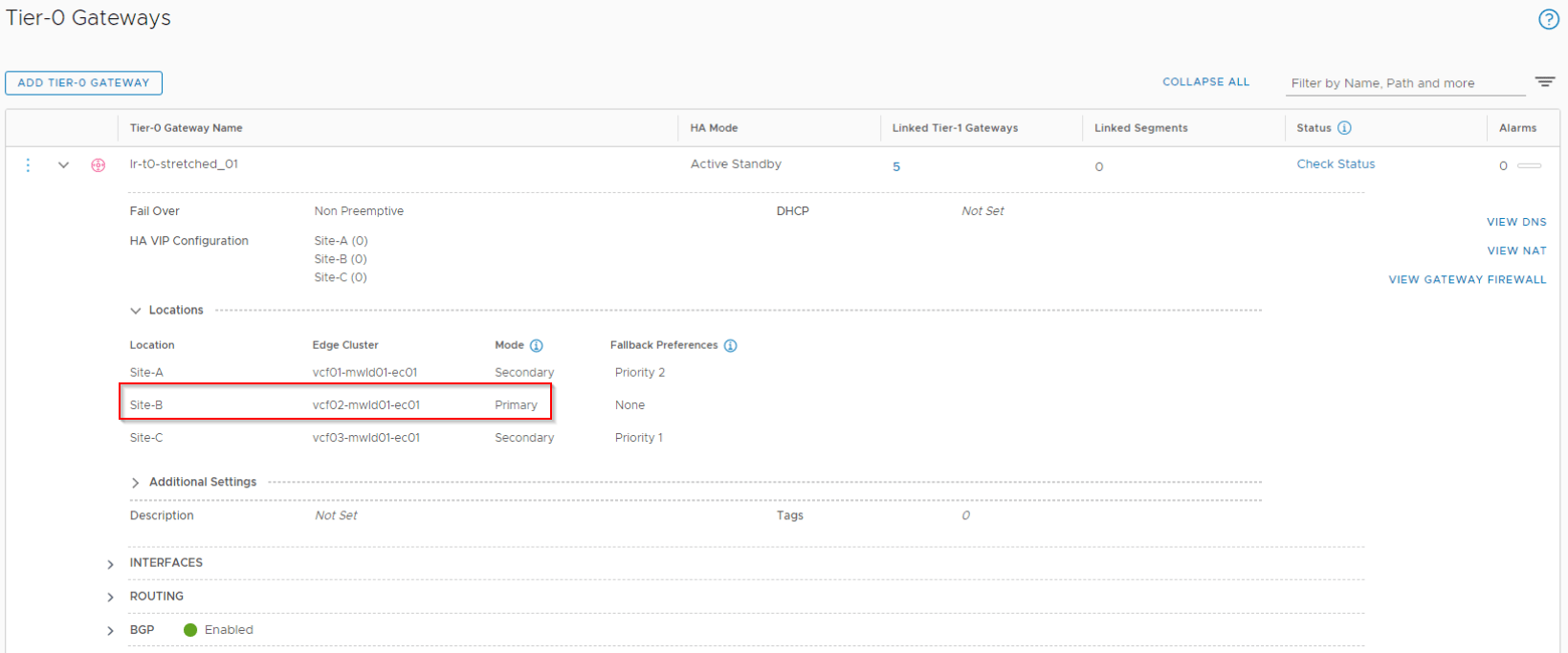
In our first topology, we have a stretched Active-Active T0 gateway with location Primary-Secondary that spans across all the locations – Site A, B and C with Site A as the primary location.
Below are the routing principles for this topology as discussed in Part 4
- Both the primary and secondary locations will advertise and receive prefixes with their respective Leaf switches in the site.
- Primary location will advertise both local as well as remote (from secondary locations) prefixes.
- Secondary locations will advertise only their local prefixes.
- All secondary locations will prefer the primary location as next-hop for egress.
- For secondary location specific prefixes (which are not received via the inter-SR iBGP relationship), next-hop points to the respective Leaf switches in the location. All other locations will point to this specific secondary location for reachability.
- To force Ingress via Site 1 (primary) only, we add a higher cost (eg: as-path prepending) to the prefixes advertised from the secondary locations.
Before Primary location (Site A) failure
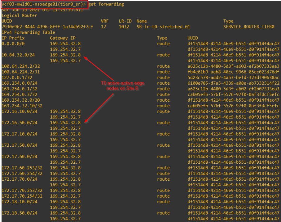
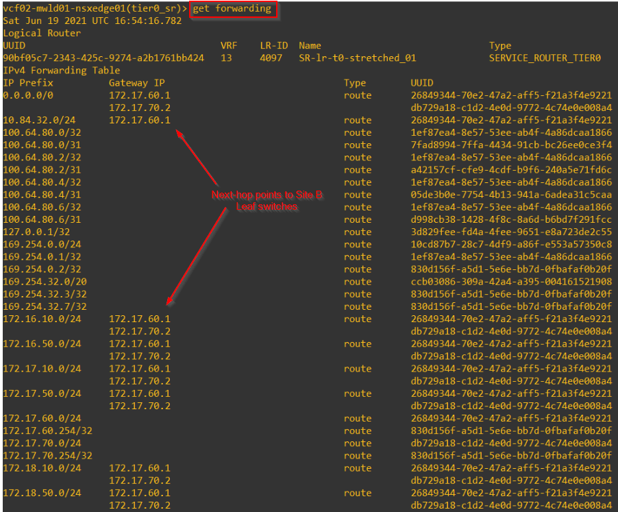
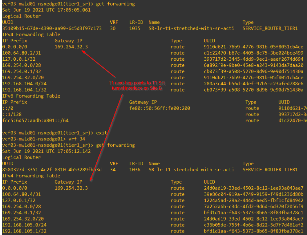
This is the T0 SR next-hop from a secondary location that points to the primary location.
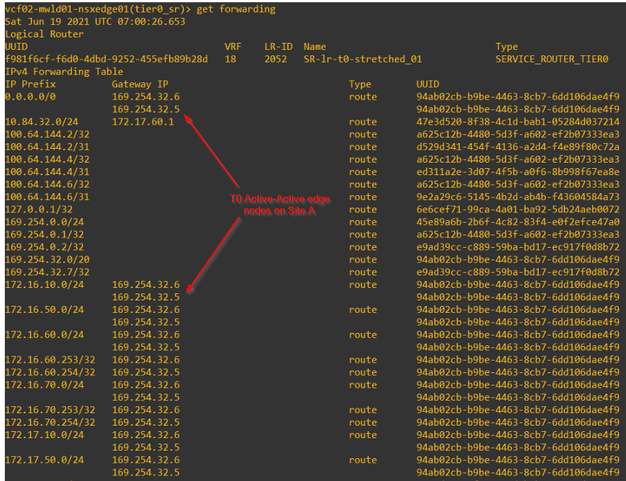
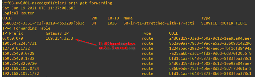
T1 SRs on secondary locations with Primary on Site A will also have the next-hop pointed to Site A.
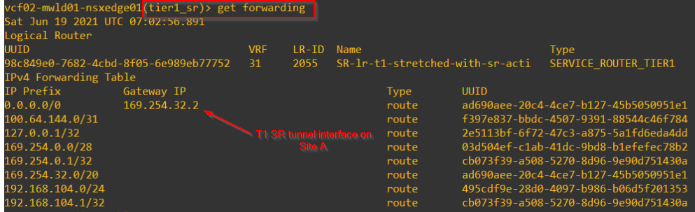
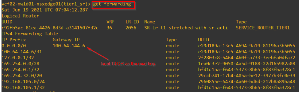
T1 SRs on secondary locations with themselves as SR primary will have the next-hop pointed locally to T0 DR.
After Primary location (Site A) failure
When Site A fails, we loose the Active GM cluster. Switchover to standby GM cluster is manual.
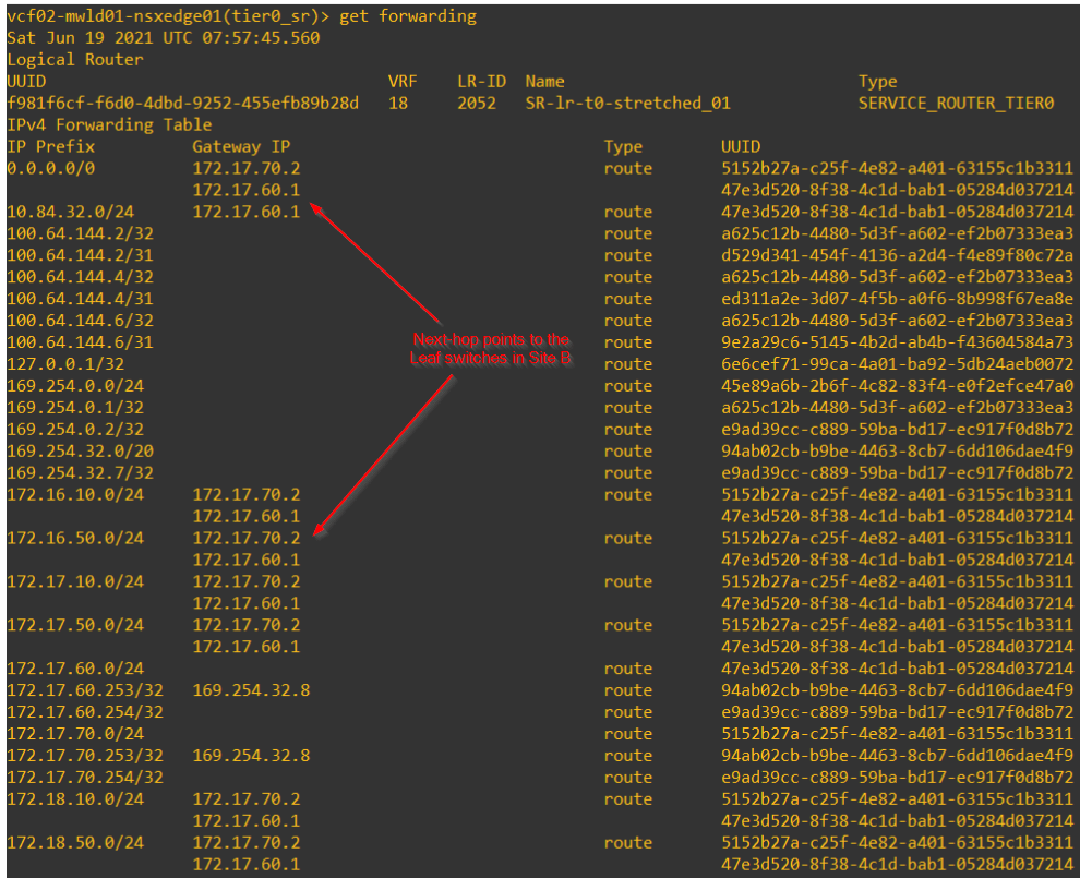
All secondary locations will have the forwarding tables of T0 SR construct next-hopping to the respective leaf switches on the location. This is because they no longer receive prefixes from primary location via inter-SR relationship. Almost a kind of local egress is happening on secondary locations at this stage and this causes assymetric routing.
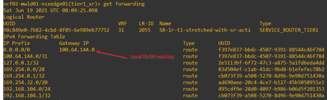
Forwarding tables of T1 SRs on secondary locations which had primary location on Site A previously, will now point towards the T0 DR construct locally. These prefixes wont be advertised, as the primary location is still on Site A.
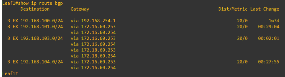
The leaf switches on secondary locations will have the below prefixes received from the respective secondary locations:
- All segments attached to non-stretched T1 gateways with span only on the respective secondary locations.
- All segments attached to stretched T1 gateways – DR only
- All segments attached to stretched T1 gateways with SR primary on that specific location.
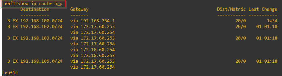
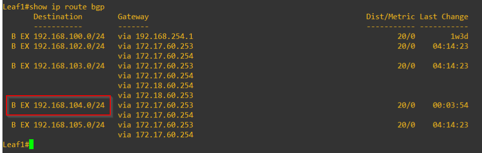
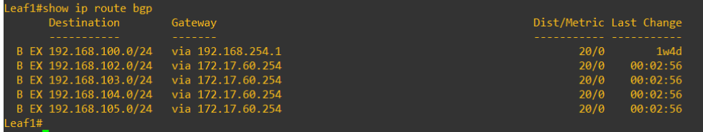
Below Leaf switch routing table is from Site B, notice we wont see 192.168.101.0/24 (non-stretched T1 on Site A) and 192.168.104.0/24 (Stretched T1 with SR primary on Site A) and hence connectivity to those segments is affected. The abovesaid segments are auto-recovered.
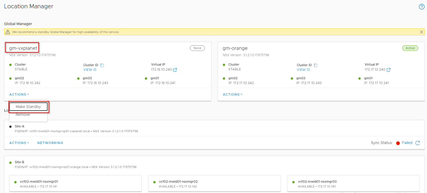
Global Manager Cluster Switchover
Switchover of a failed Active GM cluster to Standby on the other location is a manual process.
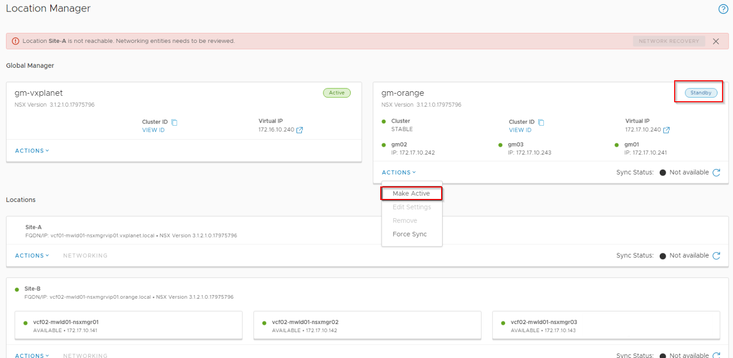
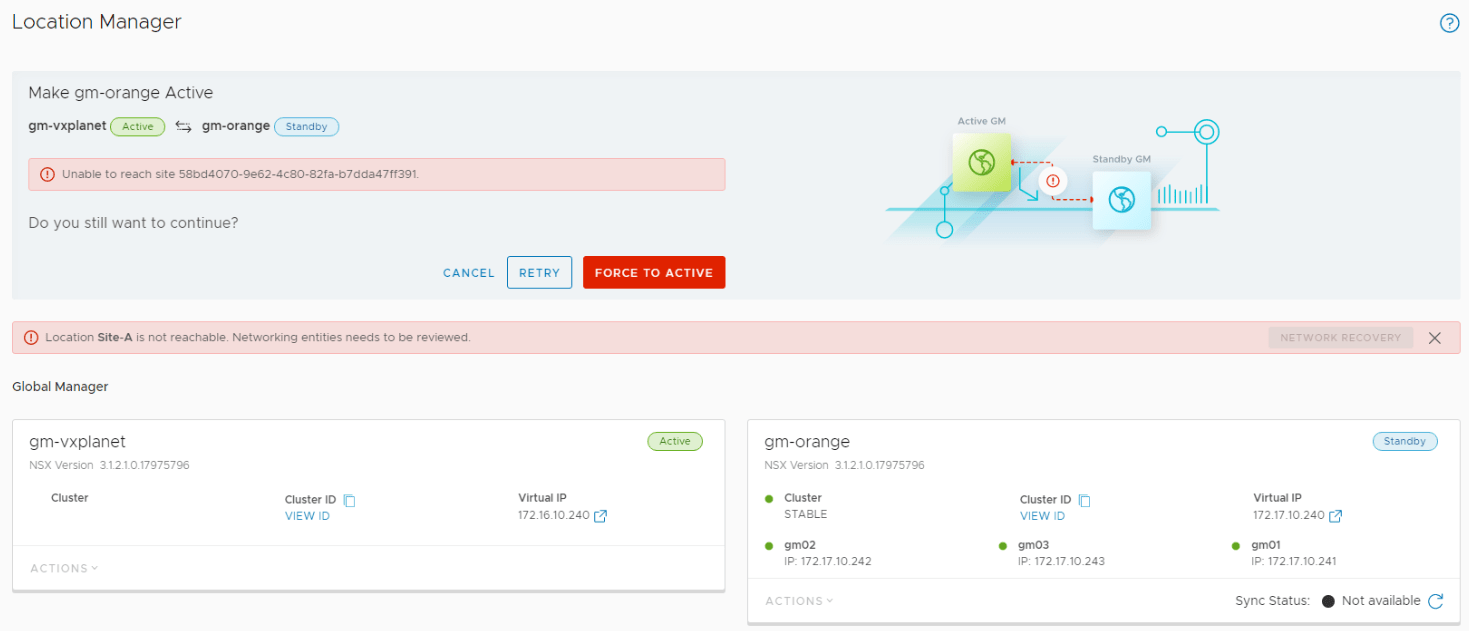
As a graceful switchover is not possible, we need a force switchover.
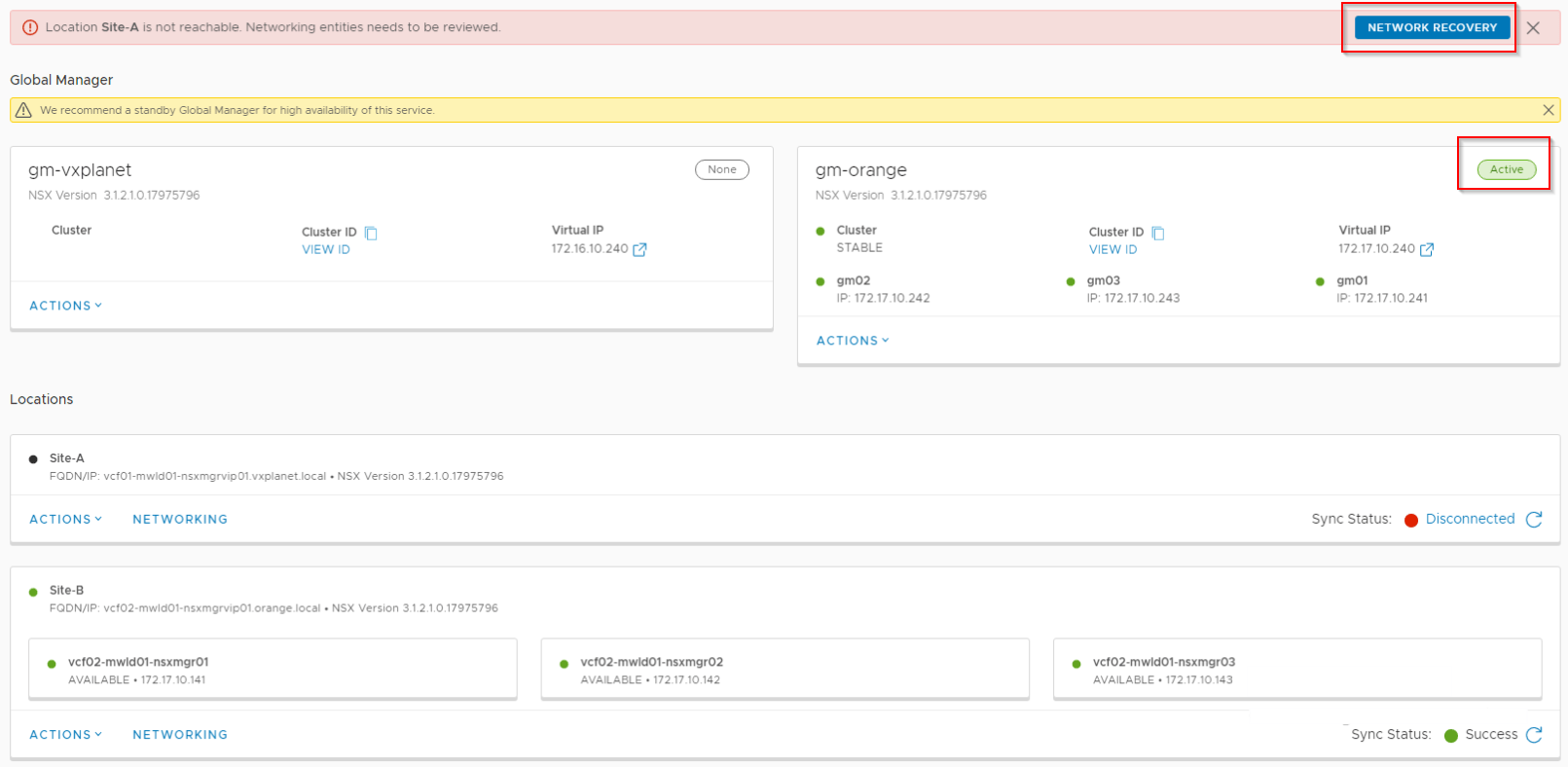
Network Recovery for T1 and T0 gateways
By running network recovery, we accomplish the below:
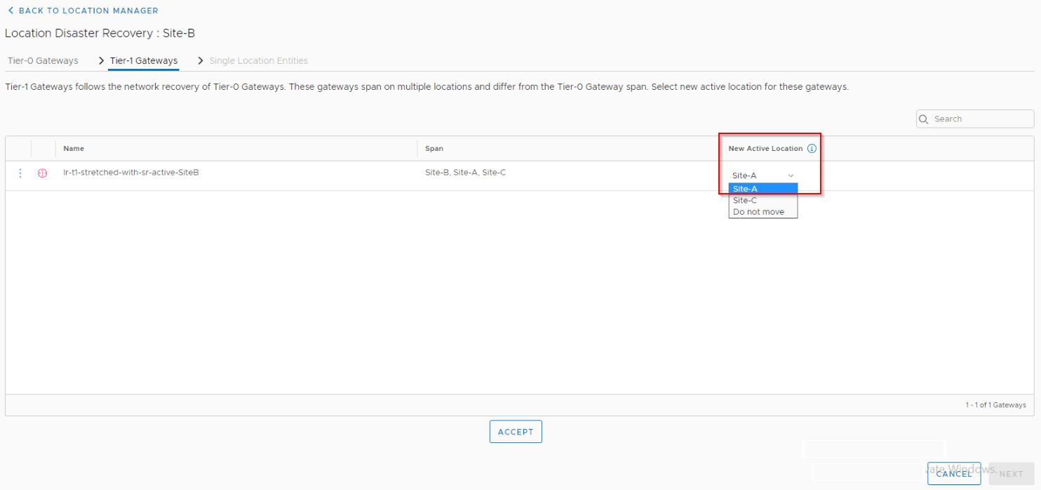
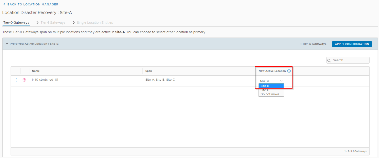
- Switchover T0 primary from Site A to Site B. All other secondary locations (Site C) will now use Site B for egress.
- Switchover any T1’s that had SR primary on Site A to Site B (or other locations). All other secondary locations (Site C) will now point their respective T1 SRs that had primary on Site A previously to Site B.
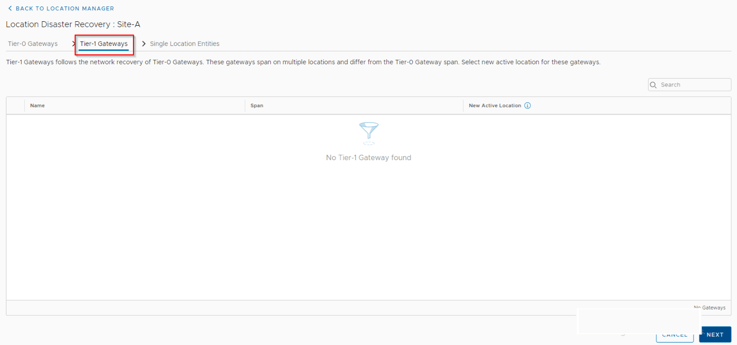
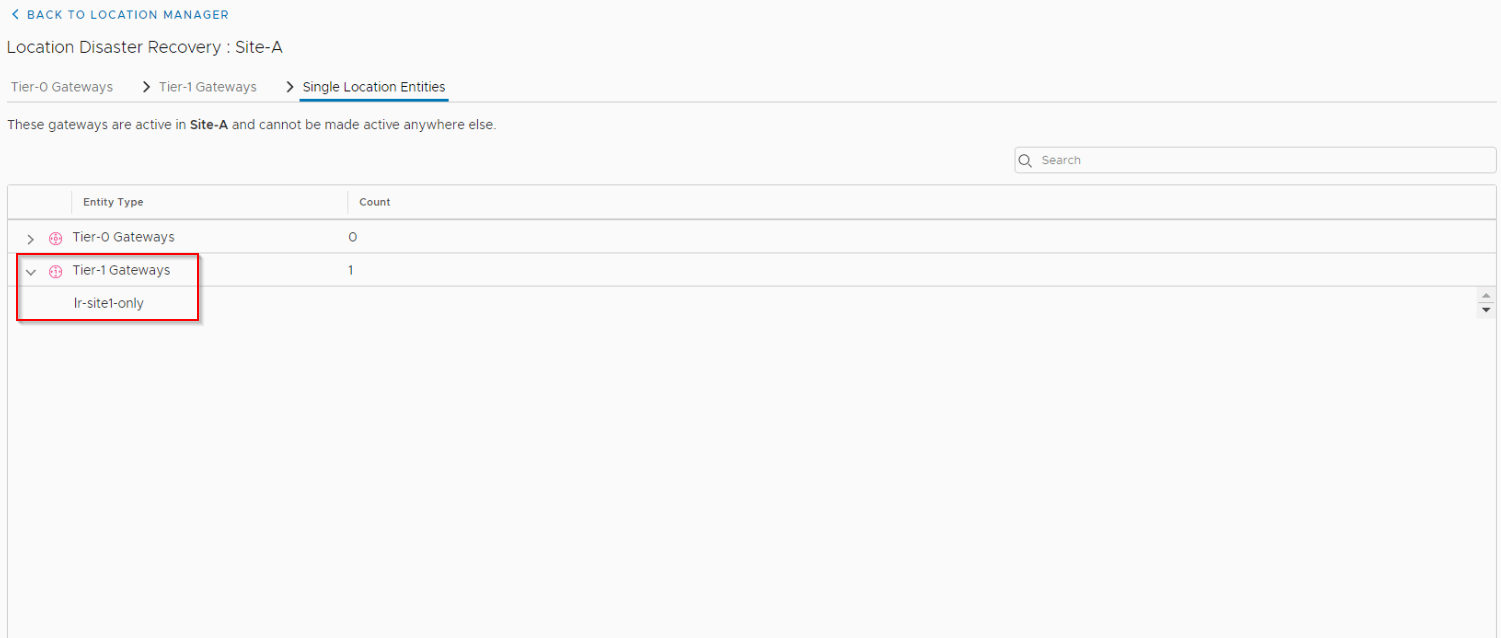
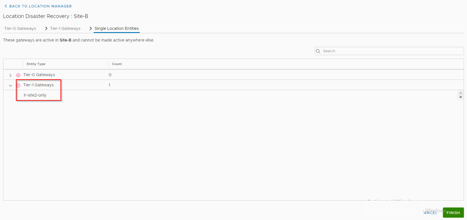
Non-stretched location specific T1 gateway’s can’t be recovered.
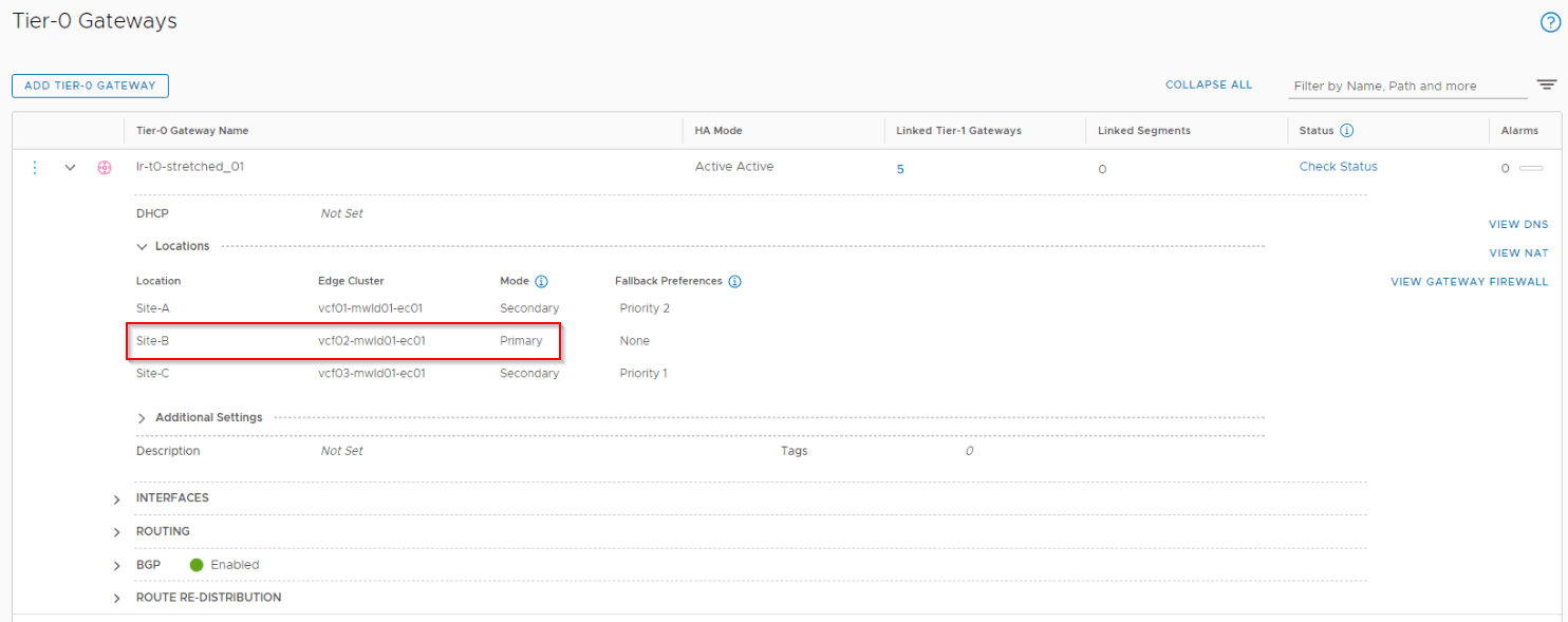
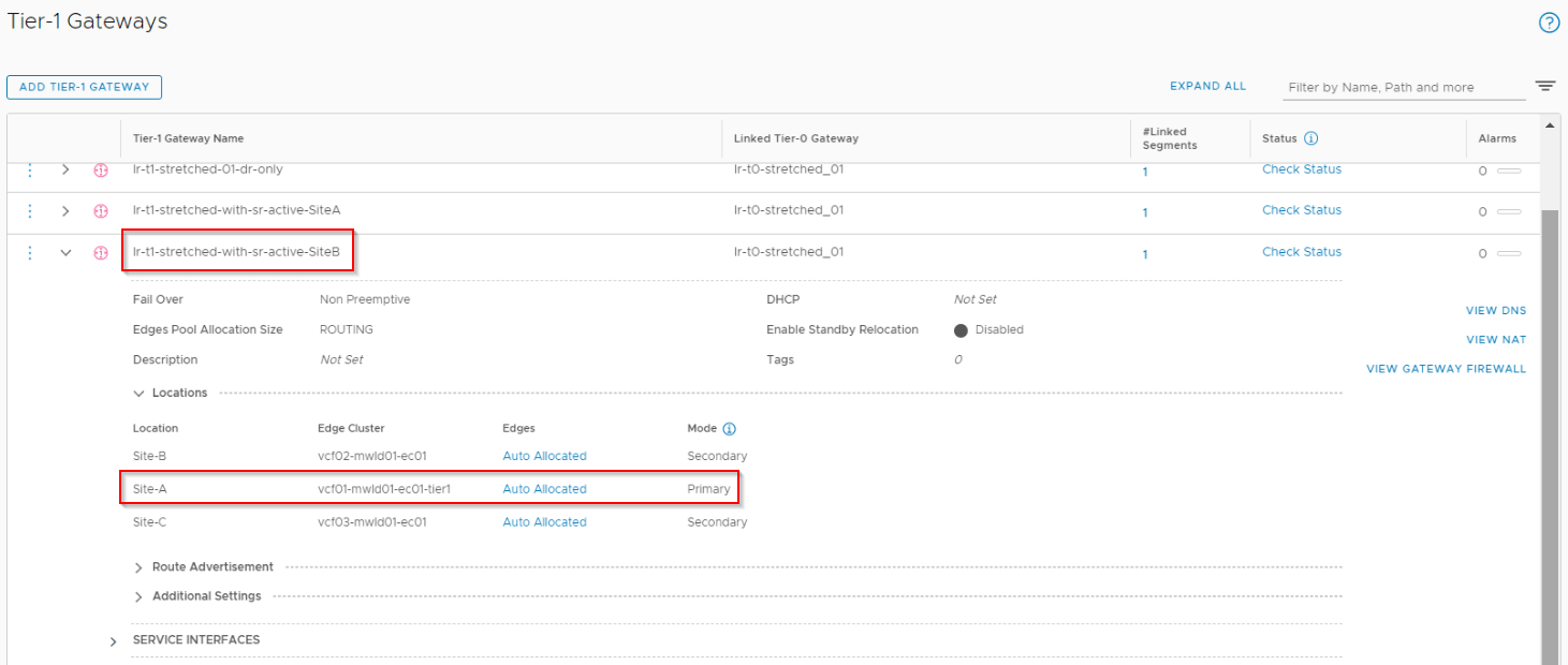
Once network recovery is done, we should see the changes reflected on the T0 and T1 gateways.
We should now see that the T1 with SR previously on Site A got recovered successfully to Site B and that the prefix is advertised to the Leaf switches from Site B.
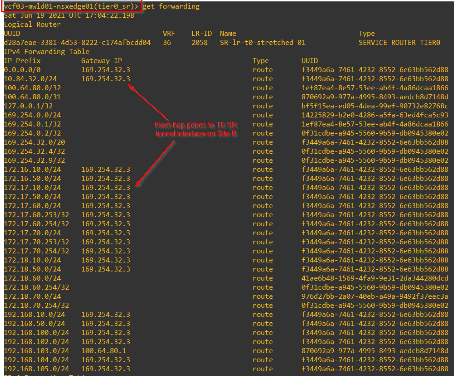
All other secondary locations (Site C) will now use Site B as primary as will next-hop to Site B for T0 SR and T1 SR next-hops.
Failback GM Active Cluster to Site A
Once we do a force failover of GM cluster to standby, we have to manually register the failed GM cluster as a standby GM cluster once it comes back.
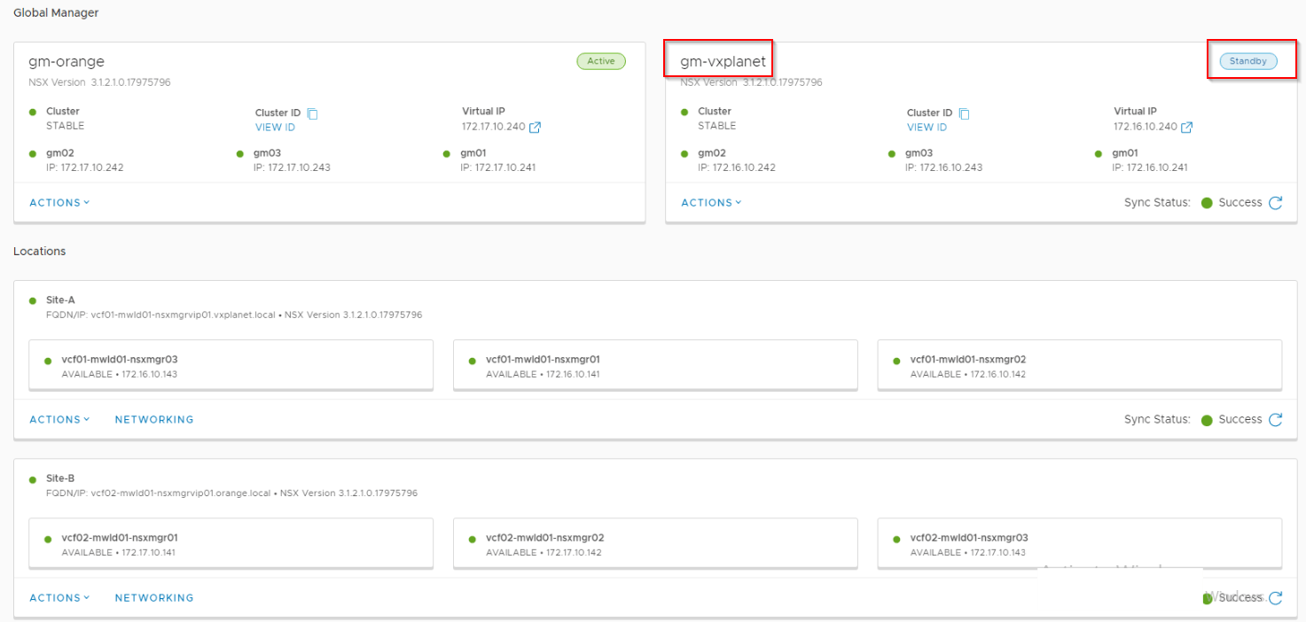
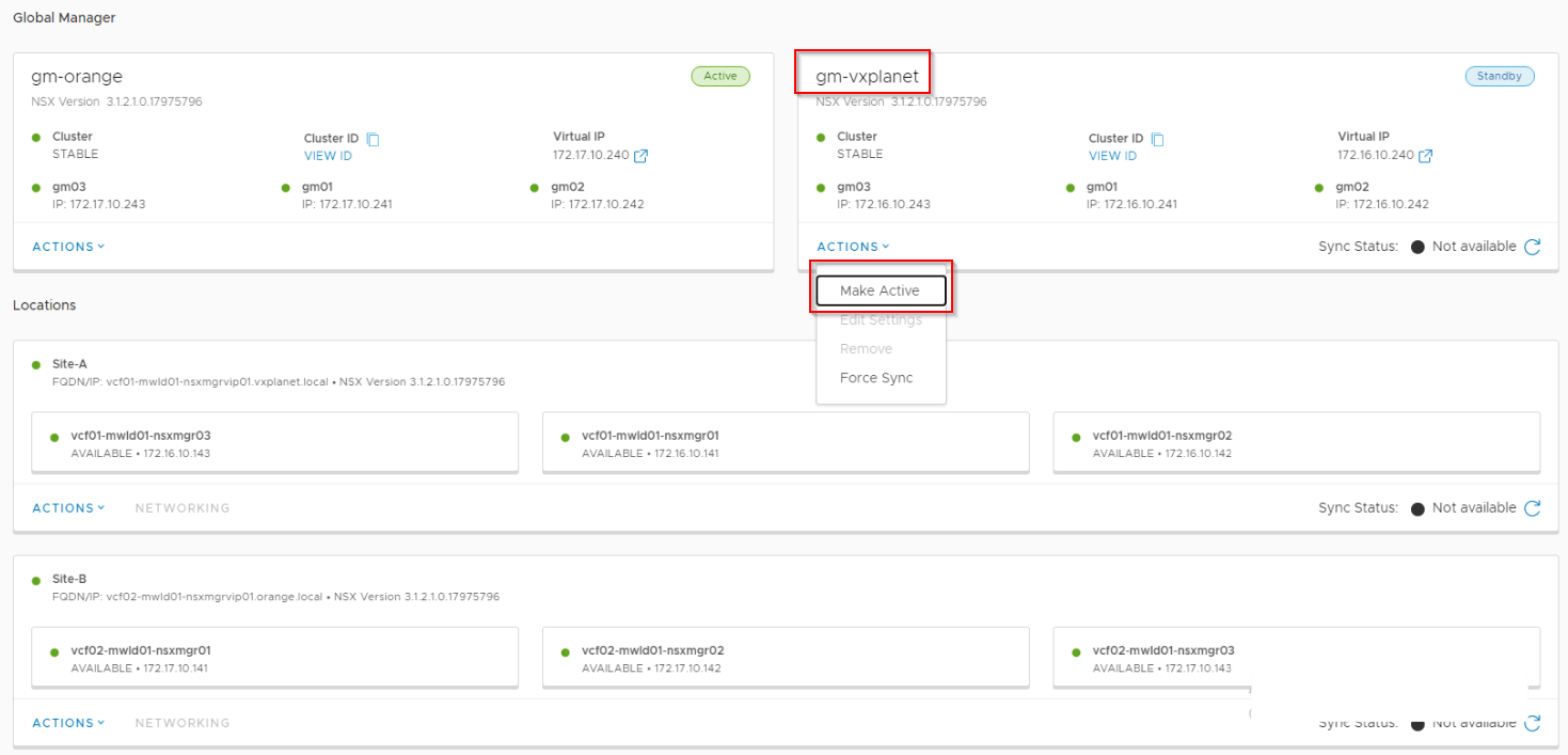
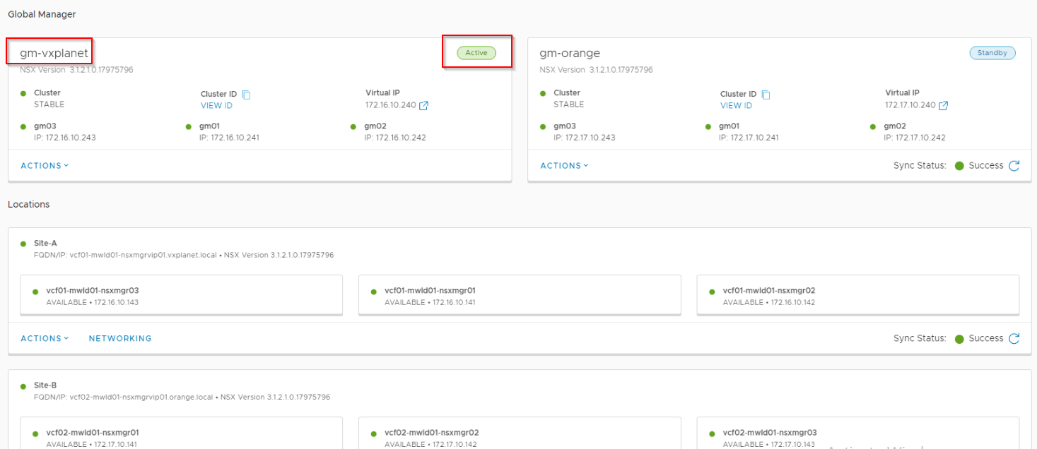
Once standby GM is registered successfully and that the sync has completed, we can do a graceful switchover.
Failback of T0/T1 Gateways to Site A
Failback of stretched gateway is a manual process that needs to be done under the specific gateway configuration.
Secondary location (Site B) failure
When a secondary location fails, we loose:
- segments attached to non-stretched T1 gateways in that secondary location.
- segments attached to stretched T1 gateway with SR primary on that specific location.
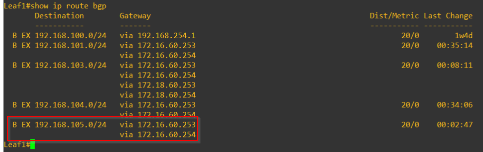
On the Leaf switches, we see both prefixes 192.168.102.0/24 (non-stretched T1 gateway in Site B) and 192.168.105/0/24 (stretched T1 gateway with SR primary in Site B) are missing.
We will do a network recovery to migrate T1 Primaries in Site B to Site A.
Non-stretched Site B specific T1 gateways can’t be recovered.
We should now see that the T1 gateway with SR Primary on Site B is switched over to Site A, the respective prefixes are advertised to the leaf switches northbound and the segments are accessible.
Stretched Active-Active Tier 0 Gateway with location All-Primary
In this second topology, we have a stretched Active-Active T0 gateway with all locations Site A, B & C as Primary.
Below are the routing principles for this topology as discussed in Part 6
- All primary locations will advertise and receive prefixes with their respective Leaf switches in the site.
- All primary locations will advertise only local prefixes of their sites. They won’t advertise remote prefixes.
- All locations will prefer their local leaf switches as next-hop for egress. All locations thus have local egress capability.
- For location specific prefixes, the next-hop points to the respective locations for egress.
- To force Ingress via a specific location, we add a higher cost (eg: as-path prepending) to the prefixes advertised from the other locations.
- Depending on the placement of T1 SR’s primary location, egress locations can vary.
When one of the primary location fails:
- Reachability to any segments attached to non-stretched T1 gateways local to the failed location is lost.
- Reachability to any segments attached to stretched T1 gateways with SR Primary on the failed location is lost.
Running network recovery will migrate the primary location of T1 SRs from the failed location to another location. The reachability is thus restored.
Procedure for running Network recovery and failback is same as the previous topology.
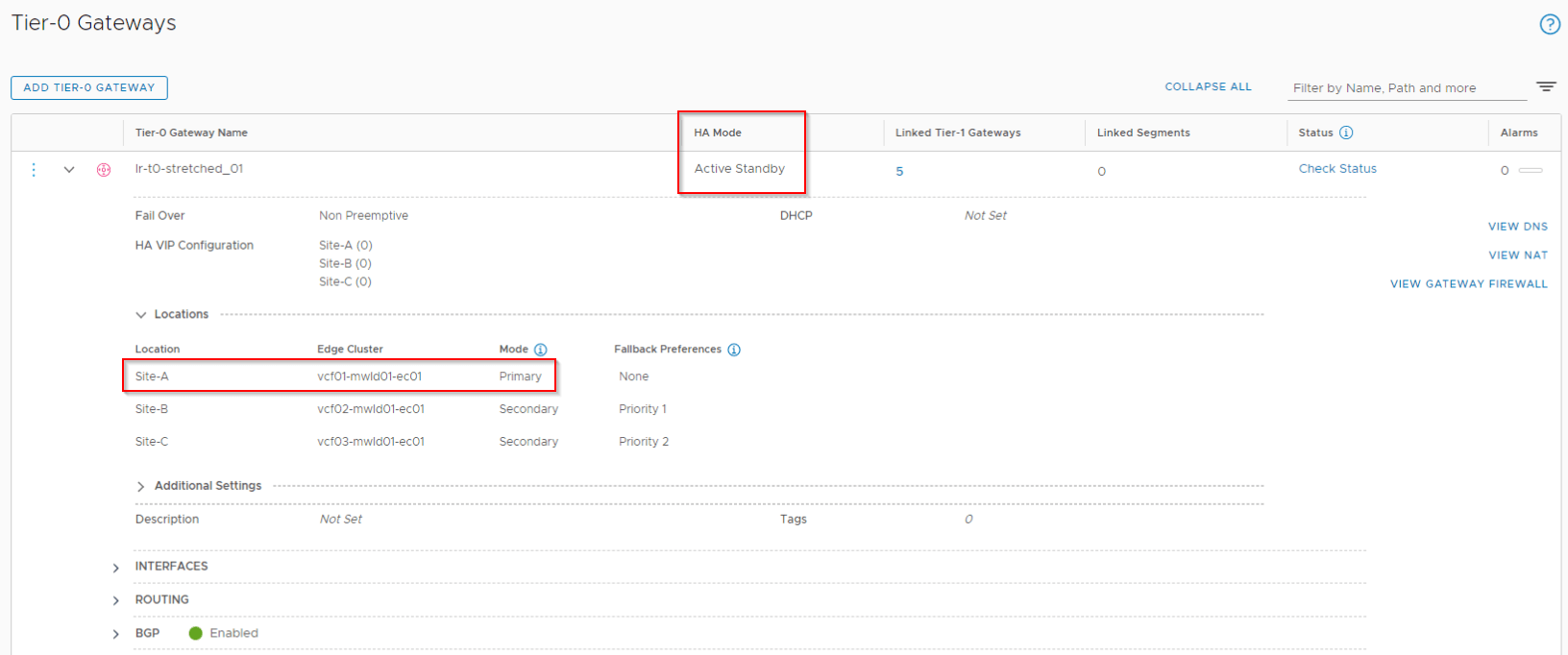
Stretched Active-Standby Tier 0 Gateway with location Primary-Secondary
In this third topology, we have a stretched Active-Standby T0 gateway with location Primary-Secondary that spans across all the locations – Site A, B and C with Site A as the primary location.
Below are the routing principles for this topology as discussed in Part 2
- Only the primary site edge nodes will advertise and receive prefixes to/from the Leaf switches and hence only the primary location is involved in N-S routing.
- Within the primary location, only the active edge node sits in the data path for N-S routing. Standby edge node uses as-path prepending for the advertised routes that makes it less preferable for the south bound traffic from the Leaf switches to the T0 gateway.
- Primary location will advertise both local as well as remote (from secondary locations) prefixes.
- Secondary locations will not advertise or receive prefixes to/from the Leaf switches.
- All secondary locations will prefer the primary location as next-hop for egress.
- Ingress automatically happens via the primary location only.
- Failure of primary location means complete cut down of N-S reachability for all the locations unless network recovery is performed manually.
After Primary location (Site A) failure
When primary location fails, all secondary locations won’t have reachability information to the Leaf networks and all N-S traffic is completely black-holed.
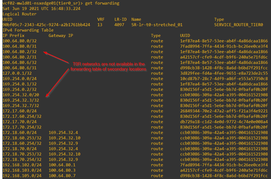
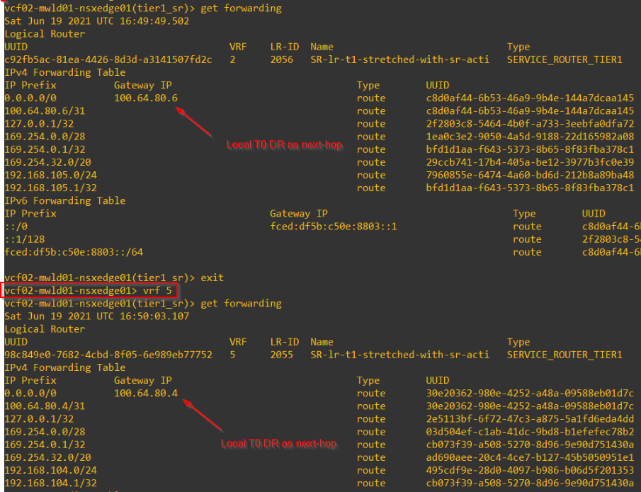
Forwarding tables of T1 SR on secondary locations with primary location on Site A will next-hop to local T0 DR construct.
As secondary locations won’t advertise any prefixes to the ToRs, all stretched and non-stretched networks are unreachable.
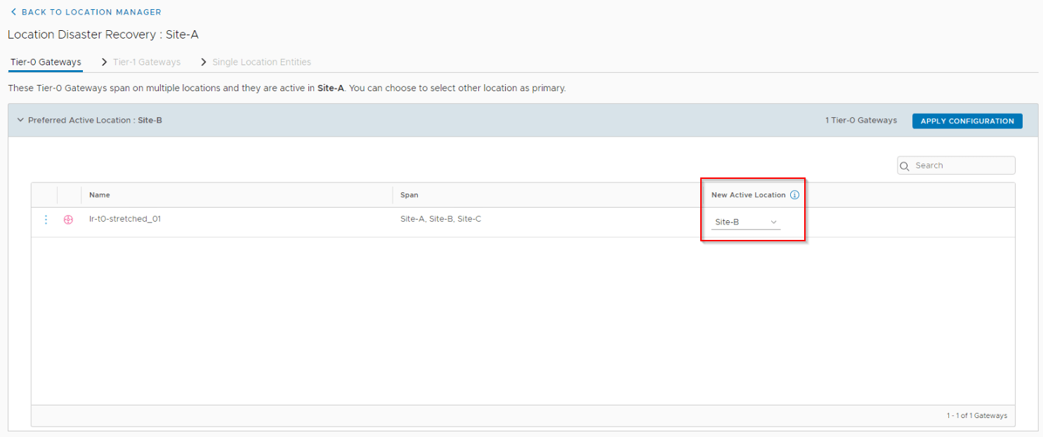
Let’s run network recovery and choose Site B to be the new primary location.
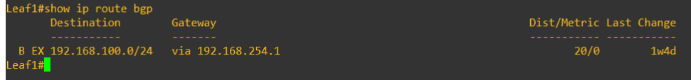
We should see Site B has now started advertising and receiving prefixes to/from the Leaf switches and network reachability is restored.
Other secondary locations (Site C) will now choose the new primary (Site B) as next-hop for T0 and T1.
Also we see under the configuration for T0 and T1 gateways, the primary location as Site B is reflected.
Once Site A comes back online the failback procedure is same as that we discussed previously with Active-Active T0 with location Primary-Secondary.
If you are still reading, Congratulations, you have reached the end of this 11-part blog series on NSX-T Federation. We covered a lot of federation from onboarding, Stretched gateway topologies, N-S & E-W packet walks, Stretched T1 placement considerations, Control Plane, dedicated edge cluster topologies, site failures and Network recovery.
If you have any questions / feedback, please reach out to me and I am glad to discuss. My contact details are on the About page.
Feel free to share it and remember I love coffee so much, and if you are interested to donate to my coffee fund, then Click Here or use my BuyMeACoffee link from the home page.
I hope this blog series was informative.
Thanks for reading.
Continue reading? Here are the previous parts of this series:
Part 1 : https://vxplanet.com/2021/04/13/nsx-t-federation-part-1-onboarding/
Part 8 : https://vxplanet.com/2021/06/02/nsx-t-federation-part-8-tier-1-gateway-placement-considerations/
Part 9 : https://vxplanet.com/2021/06/09/nsx-t-federation-part-9-federation-control-plane-explained/