

Introduction
NSX-T federation offers a centralized management pane to configure networking and security across locations in a multi-site deployment. Federation introduces the concept of a Global manager (GM) cluster which pushes the configuration to different locations based on the object span. The site-specific NSX-T managers (called local managers) receives the configuration and implements it locally. GM maintains only the management plane and doesn’t maintain any control plane information for the sites. The local managers are responsible for the control plane information for their respective sites and syncs the control plane information between other LMs across locations. The control plane information includes both network (Eg: MAC tables, ARP tables, TEP tables etc) and security (group memberships, DFW rules etc) which are then pushed down to the data plane.
The Global manager clusters are deployed in Active / Standby form across two different locations. In the event of a site failure, the standby GM takes over the management plane functionality (currently a manual process) and depending on the networking and security object span, applications continue to run on the different site.
Note : There is another GM deployment model where the Active GM nodes span across sites. This eliminates a Standby GM cluster to reduce the footprint of the overall deployment. This is only for sites which are close and have low latencies (~ 10ms) between them.
We will cover a lot of federation in the upcoming posts in this series, stay tuned.
Part 1 – Federation onboarding
Part 2 – Stretched A/S Tier 0 Gateway with location Primary/Secondary
Part 3 – Stretched A/S Tier 0 Gateway with location Primary/Secondary – Packet Walk
Part 4 – Stretched A/A Tier 0 Gateway with location Primary/Secondary
Part 5 – Stretched A/A Tier 0 Gateway with location Primary/Secondary – Packet Walk
Part 6 – Stretched A/A Tier 0 Gateway with location All-Primary
Part 7 – Stretched A/A Tier 0 Gateway with location All-Primary – Packet Walk
Part 8 – Tier 1 Gateway Placement Considerations
Part 9 – Federation Control Plane
Part 10 – Dedicated Edge Cluster for Stretched Tier 1 Gateways
Part 11 – Site Failures and Network Recovery
In this article, we will get started with federation and cover the onboarding process, here is the breakdown:
- Deploying the Active global manager cluster in Site A
- Deploying the Standby global manager cluster in Site B
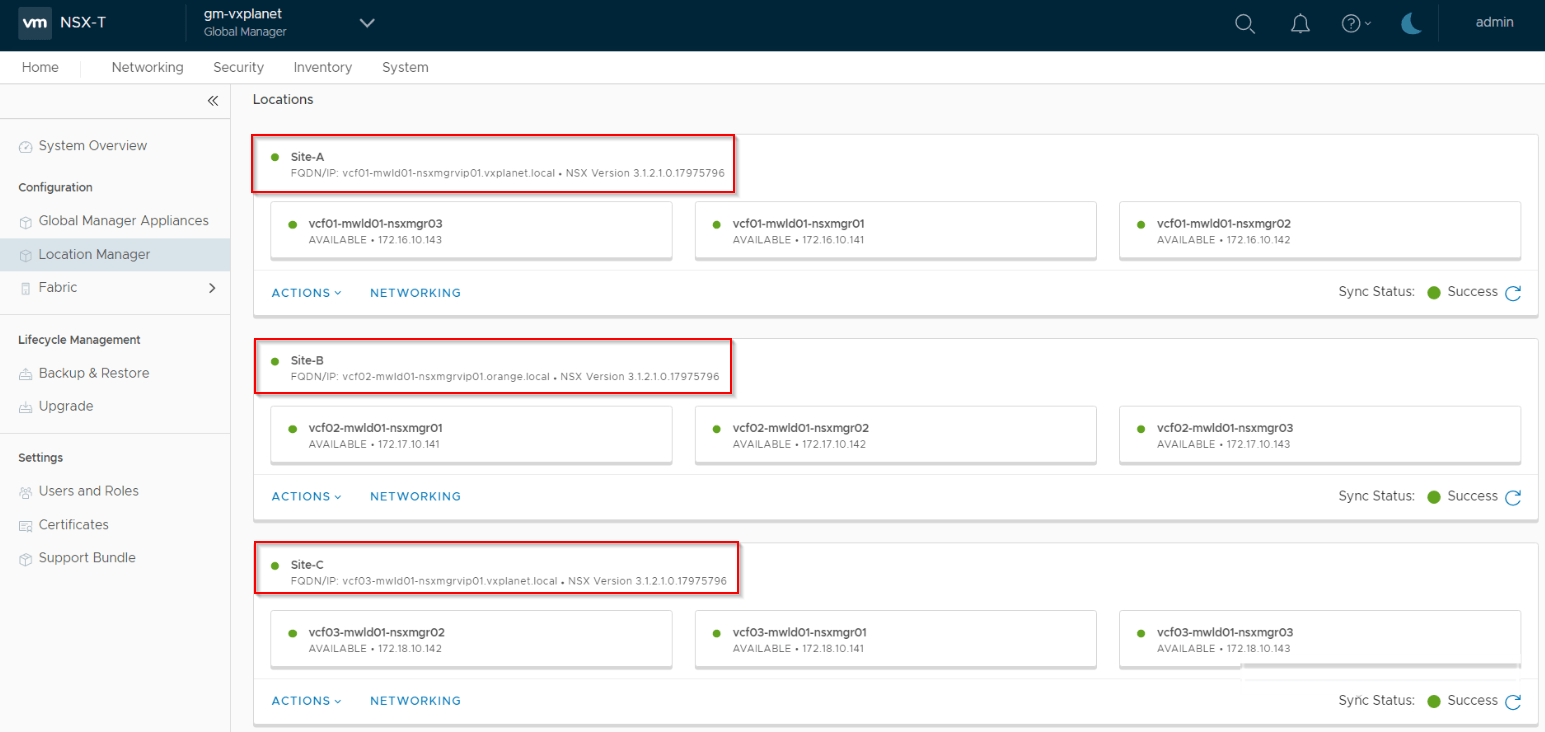
- Onboarding location managers (Site A, Site B & Site C)
- Configuring RTEP
Let’s get started:
Current infrastructure
Let’s look at the current infrastructure at a high level. Local site configuration has already been covered in my previous articles and is outside the scope of this blog series.
- This is a multisite infrastructure with 3 sites – Site A, Site B and Site C.
- Each site is managed by it’s local vCenter Server.
- Each site has it’s NSX-T local manager cluster. The local vCenter server is added as a compute manager to the LM to automate the deployment of additional LMs.
- Each site has only one vSphere cluster (a shared management, compute and edge cluster)
- Each site has an Edge cluster with 2 edge nodes. This is a shared edge cluster for all T1 services, T0 routing and RTEP.
- Site recovery tools are not configured (due to resource limitations) but it is assumed that the sites has SRM configured to orchestrate DR in case of site failures.
Here is the VLAN and subnet schema used for the sites:

Here is the FQDN-IP schema used for the infrastructure components in the sites. Site A hosts the Active GM cluster and Site B hosts the Standby GM cluster.


Deploying the Active global manager cluster in Site A
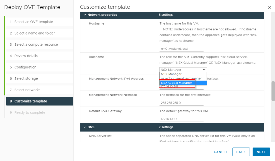
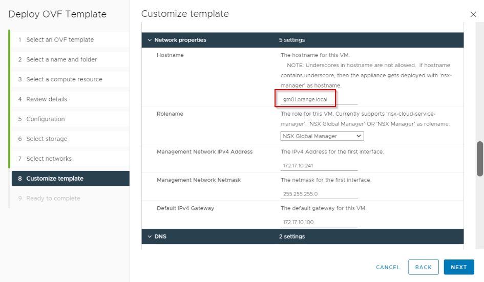
Global manager is deployed using the same ova template that is used to deploy the local managers with the role selected as ‘NSX Global Manager’. Active Global manager cluster is chosen to be on Site A.
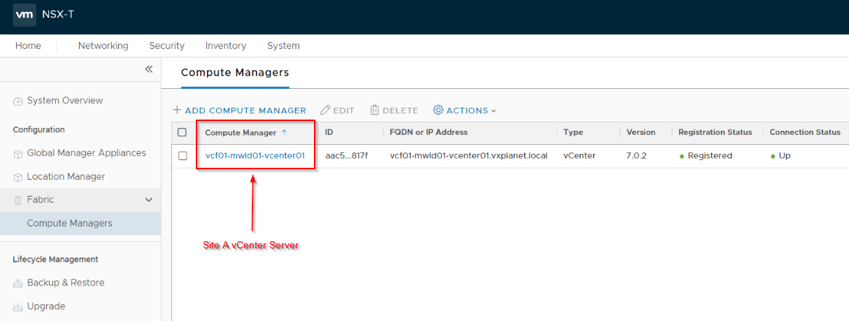
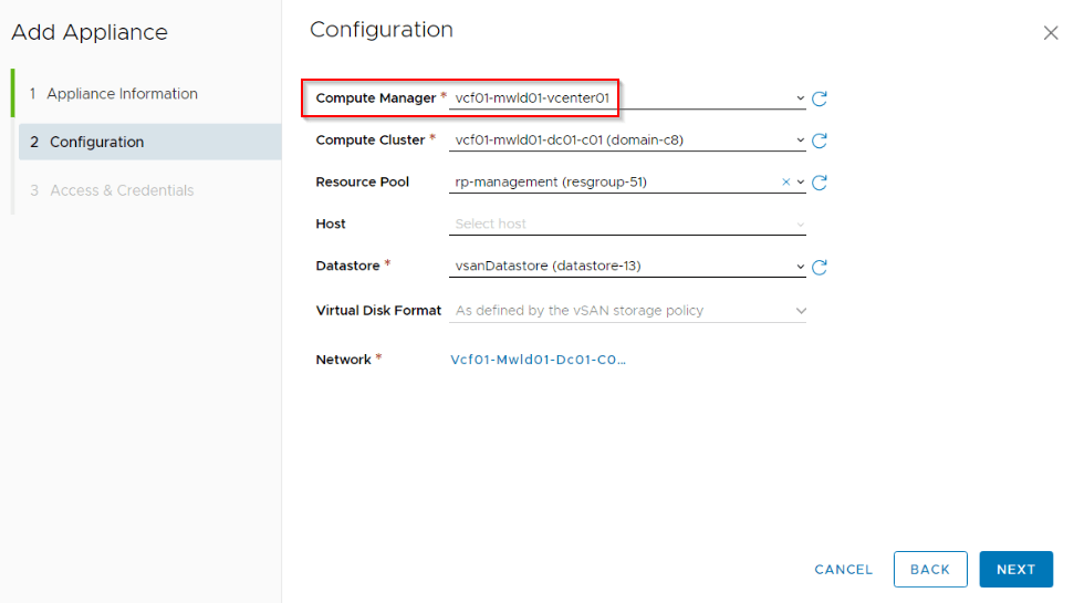
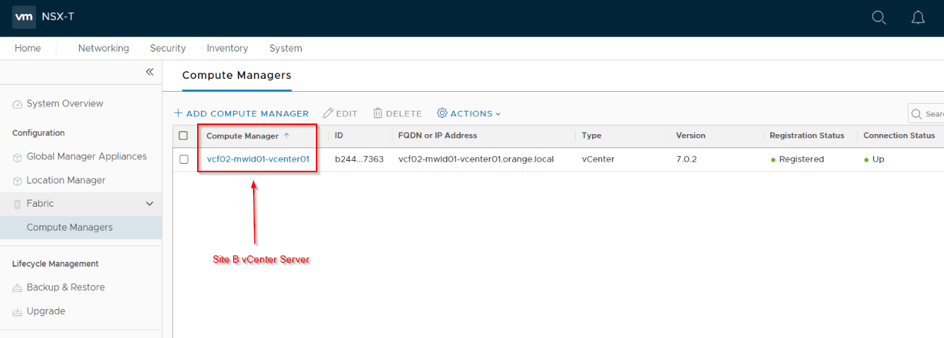
Once the GM is deployed, add Site A vCenter server as a compute manager to GM. This is needed to orchestrate the deployment of additional nodes of the GM cluster.
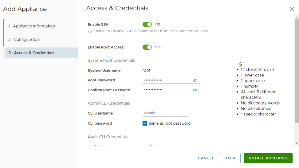
Deploy the second and third GM nodes to form a GM cluster at Site A
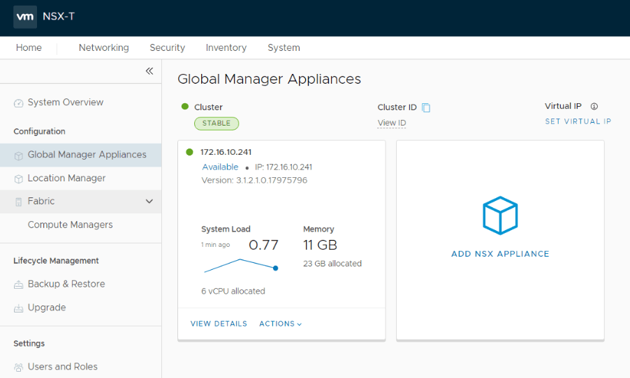
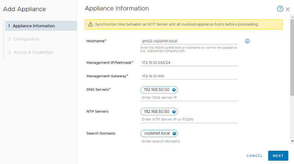
FQDN, IP addresses and other infrastructure details were mentioned earlier.
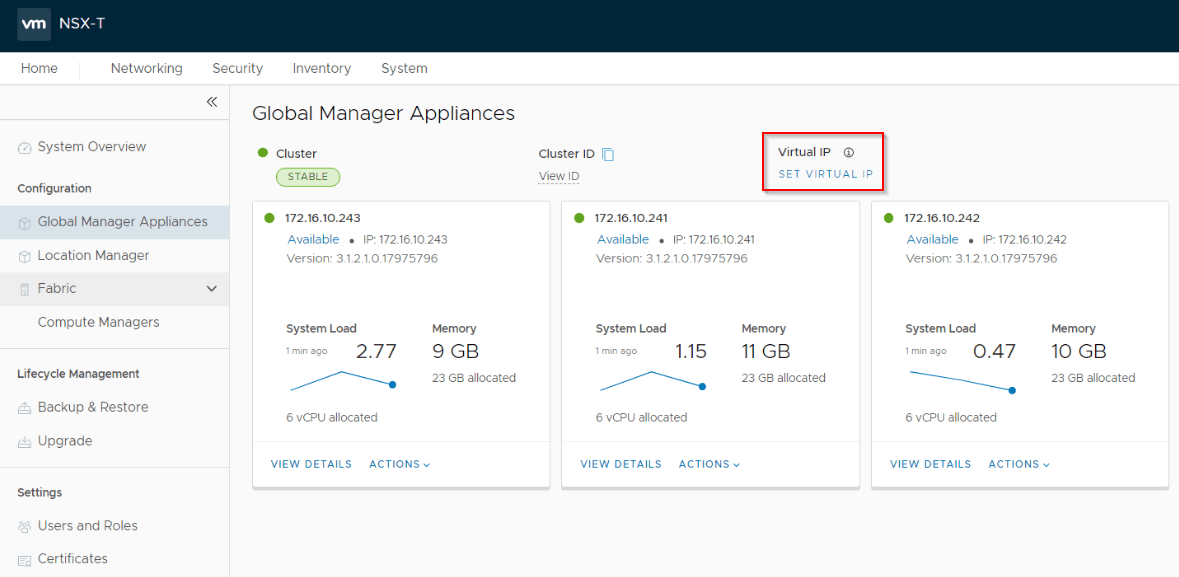
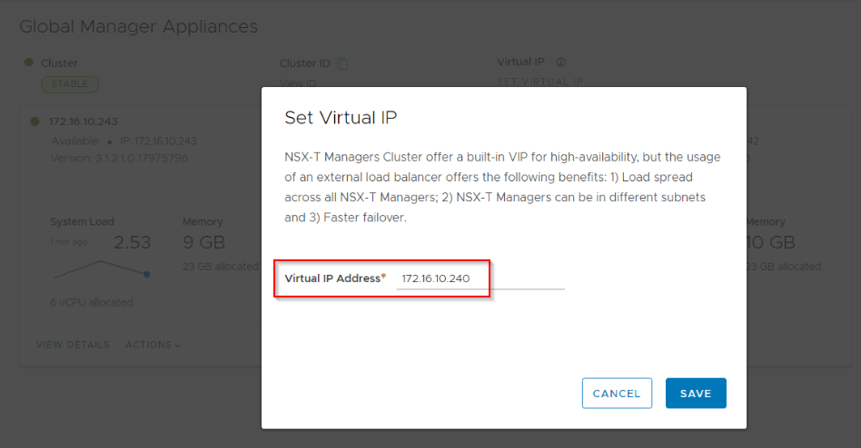
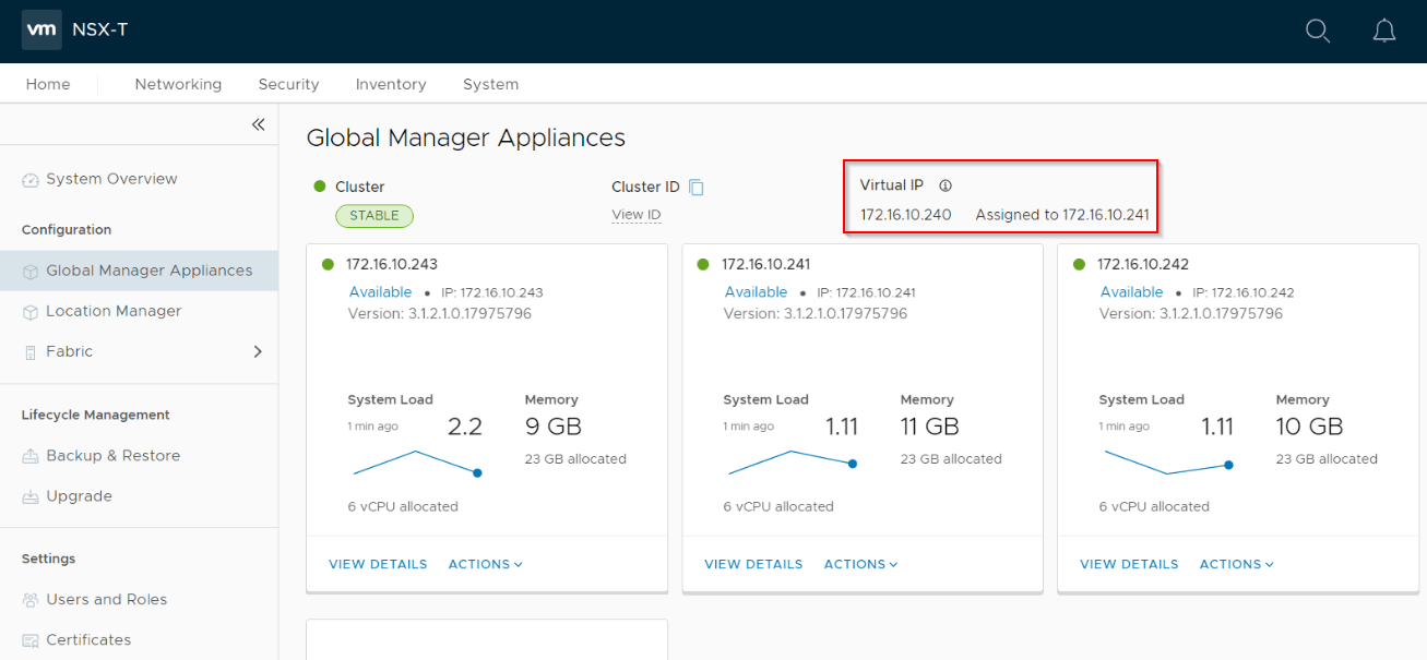
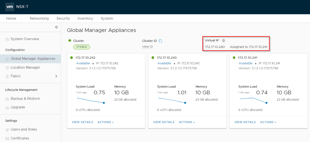
Once the three node GM cluster is up and the sync has completed, set a VIP for the cluster.
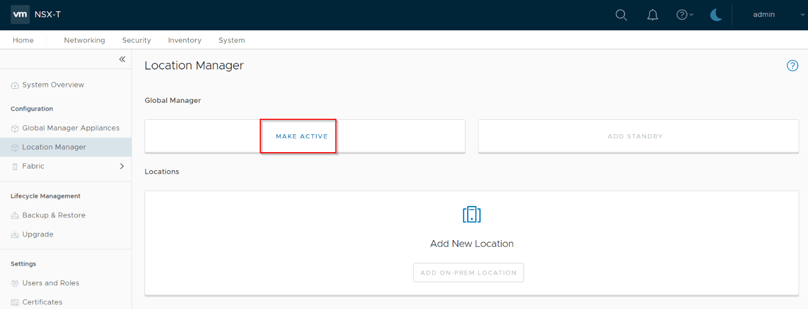
Next, promote the GM cluster on Site A as ‘Active’.
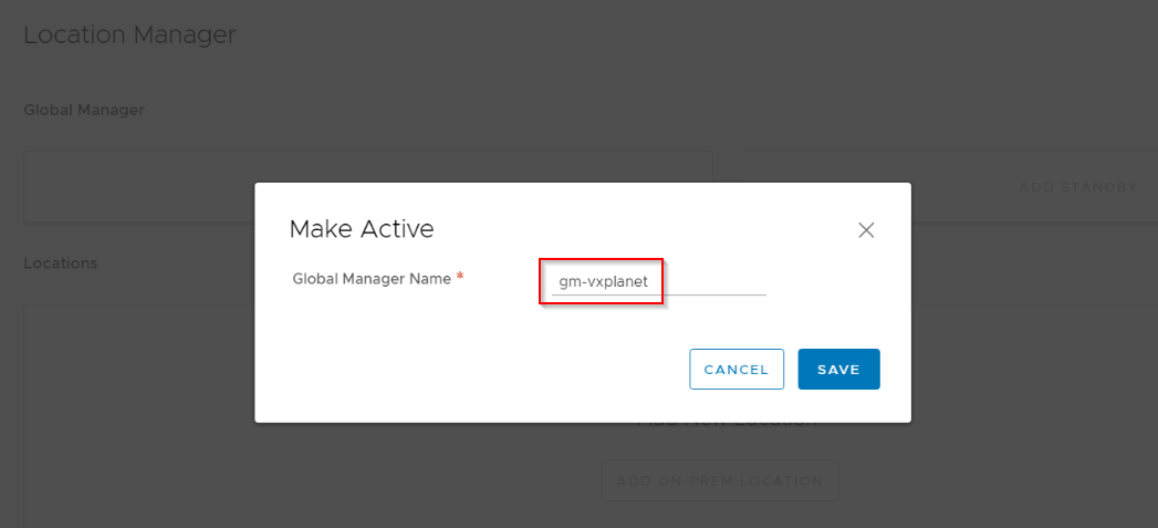
Provide an unique name for the Active GM cluster.
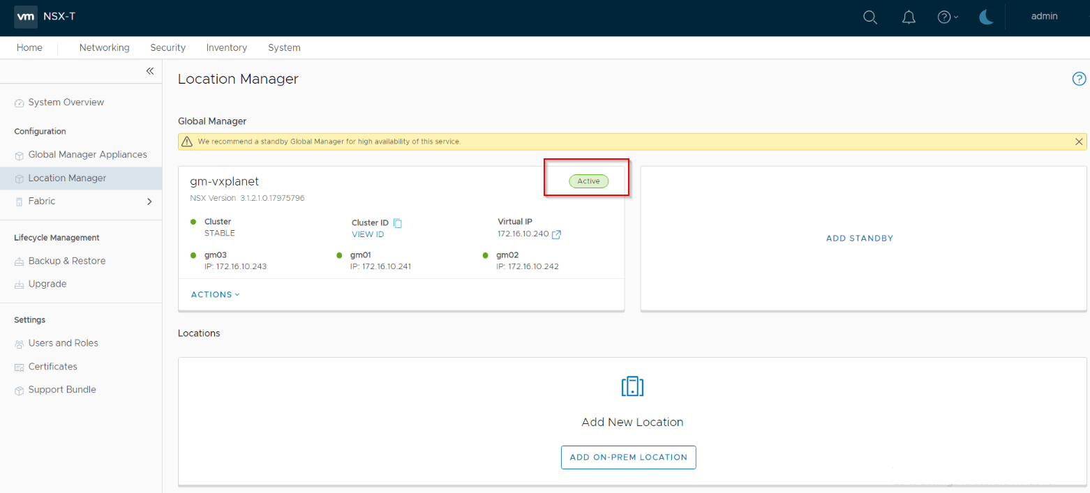
We now have an Active GM cluster running in Site A. Next, let’s add the Standby GM Cluster in Site B.
Deploying the Standby global manager cluster in Site B
The procedure is exactly similar to above except that we are deploying to Site B and the IP/FQDN/domain are different.
Add Site B vCenter Server as compute manager to the GM and deploy additional two nodes to form a GM cluster.
From the Active GM in Site A, add the Site B GM as Standby.
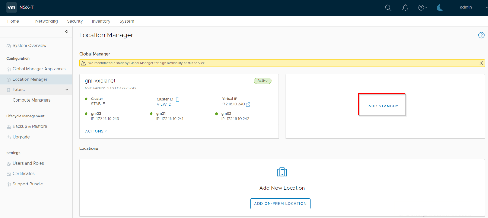
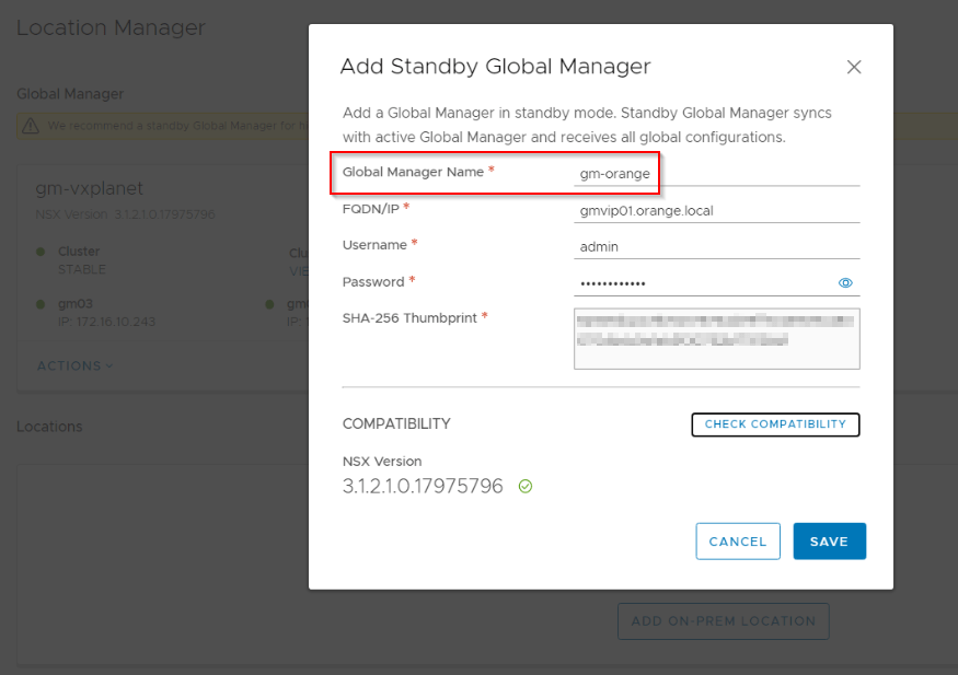
Provide a unique name for the standby GM Cluster. Also make sure we use the VIP and not the individual node FQDN so that connectivity is still maintained when any standby GM node goes down.
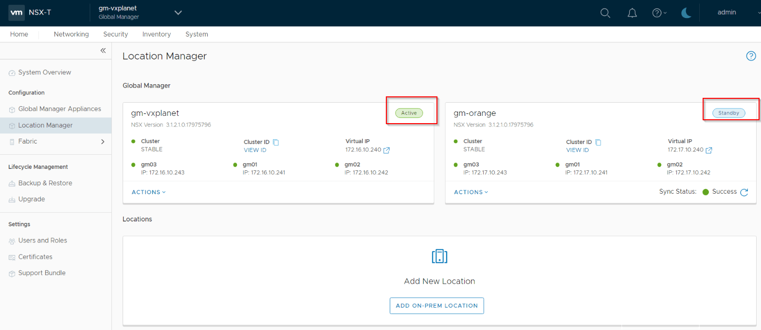
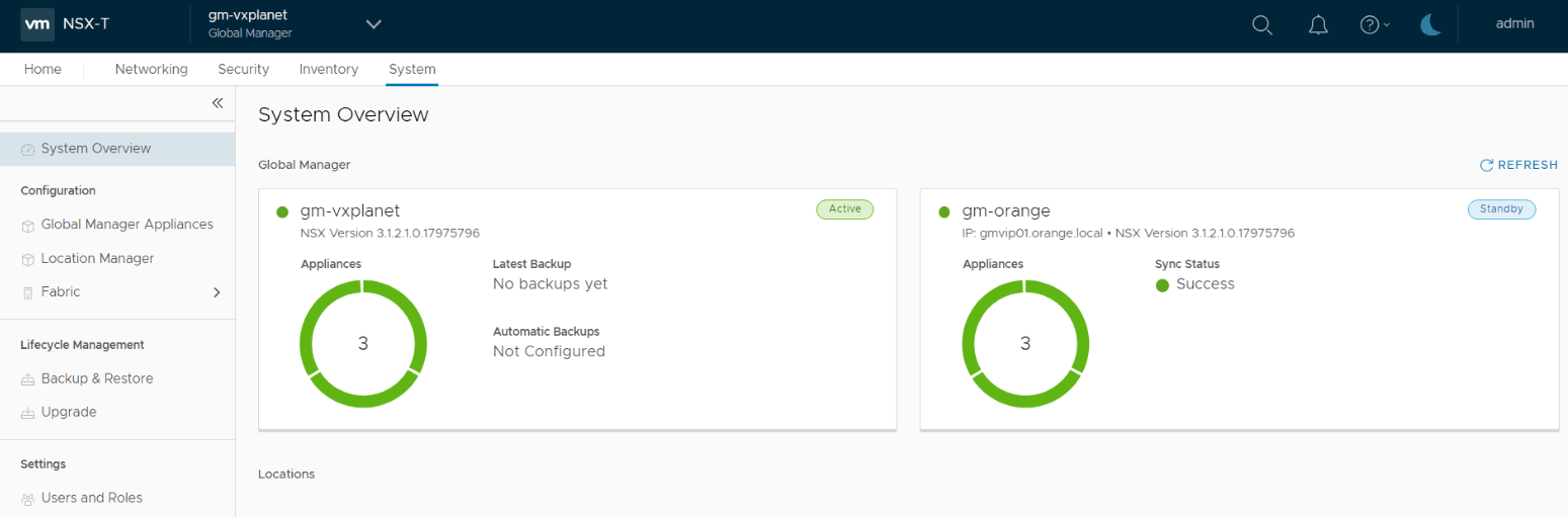
Once the standby GM is added and the full sync has completed successfully, we can now onboard the local managers from each location.
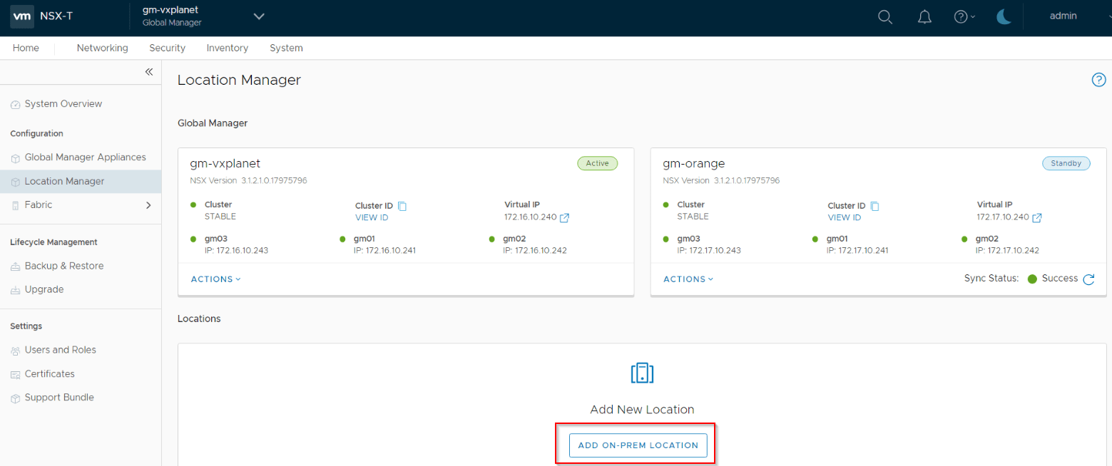
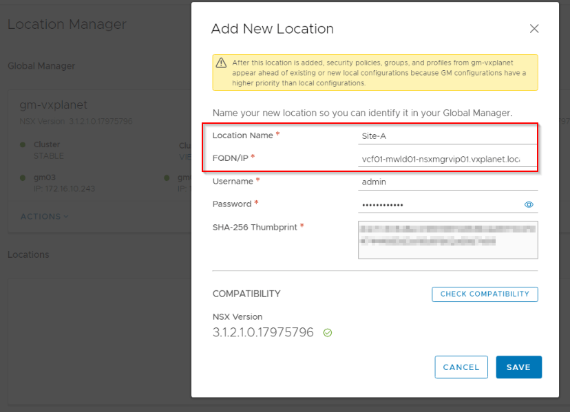
Onboarding local managers
From the Active GM, we can onboard the LMs from each location. Make sure we use the LM VIP to ensure connectivity from the GM in case any of the LM node goes down.
Once all the LMs are added, we can now configure the Remote TEPs (RTEP) on the edge nodes of each location.
Configuring RTEP
Remote TEP (RTEP) interfaces are configured on each edge node in the edge cluster within a location to support stretched networking. RTEP is needed only if we want to enable inter-site communication. RTEP needs to be configured on a different VLAN than the edge TEP interfaces. There can be only one RTEP interface per edge node at present.
Once RTEP is configured, each edge node establishes a full mesh geneve tunnel (internal segment) to edges in other locations. Heartbeats are sent across this geneve tunnel (internal segment) to detect remote edge availability. Also each edge node establishes a full-mesh iBGP with edges in other locations over the RTEP interface on the IPV6 address family – more on this in the subsequent articles.
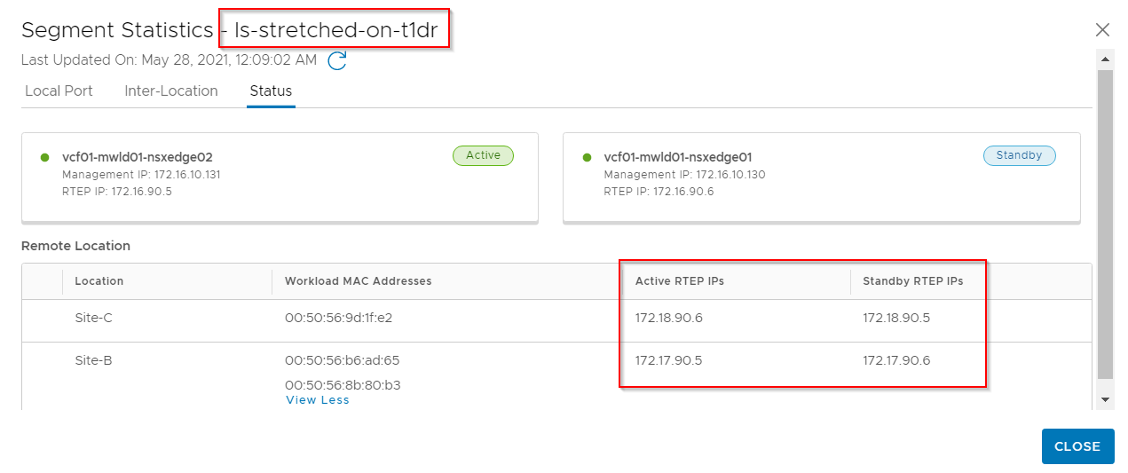
Unlike the previous NSX-T multi-site solution, hypervisor TEPs wont establish geneve tunnels across sites for stretched networking (L2). Any L2 traffic across sites will be tunneled between the RTEPs across sites. Each stretched L2 segment will have an L2forwarder construct on the RTEP enabled edge nodes. L2forwarder construct can be Active/Standby or Active/Active based on the deployment, hence RTEP edge nodes will be responsible for inter-location communication for the specific segment – more on this later.
Below is the L2forwarder details of a segment that is stretched across all the three locations. For eg, if a VM on site A needs to communicate with a VM on Site B on the segment ‘ls-stretched-on-t1dr’, the intersite traffic will be tunneled between 172.16.90.5 (RTEP Edge Site A) and 172.17.90.5 (RTEP edge Site B)
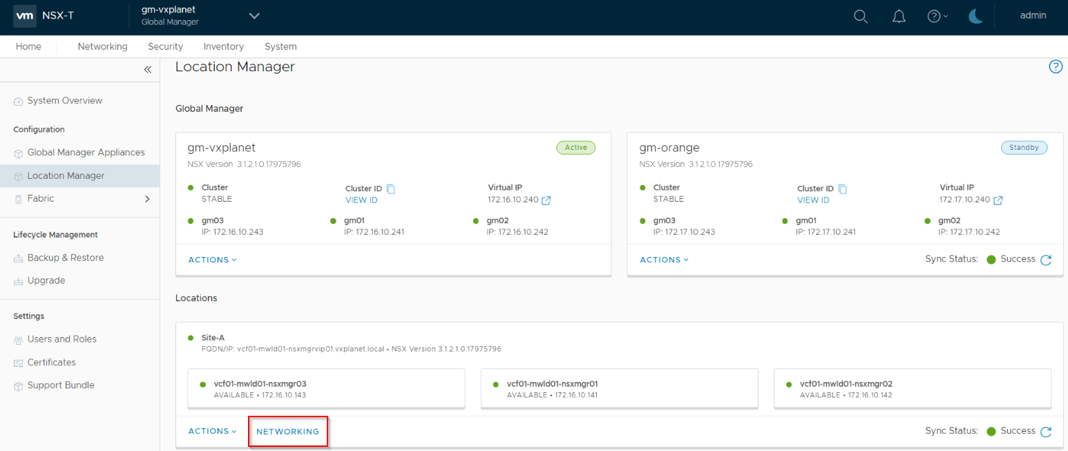
Now let’s configure RTEPs on each location.
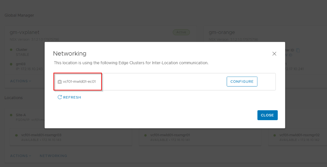
Click on the ‘Networking’ option under each Local Manager.
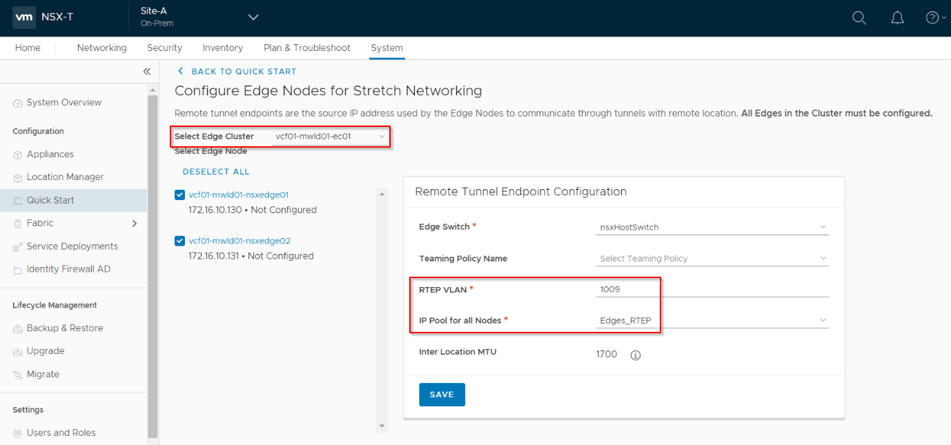
If the LM has multiple edge clusters (separate T1 and T0), choose the one for RTEP communication. In most cases, it will be the edge cluster for T0 Gateway.
Choose the RTEP VLAN (based on the IP schema we discussed earlier – For Site A, it is 1009). We do have an option to apply a named teaming policy, so that the RTEP traffic can be steered over a specific edge uplink.
It’s recommended to ensure unfragmented RTEP communication across sites, make sure we have an end-to-end MTU of atleast 1700.
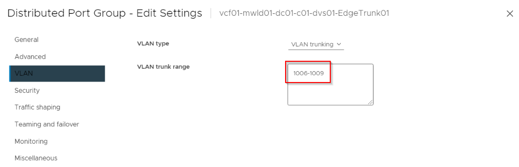
Make sure that the Trunk VLAN port groups on the host VDS where the edges are uplinked, allows the RTEP VLAN tags (in this case, VLAN 1009).
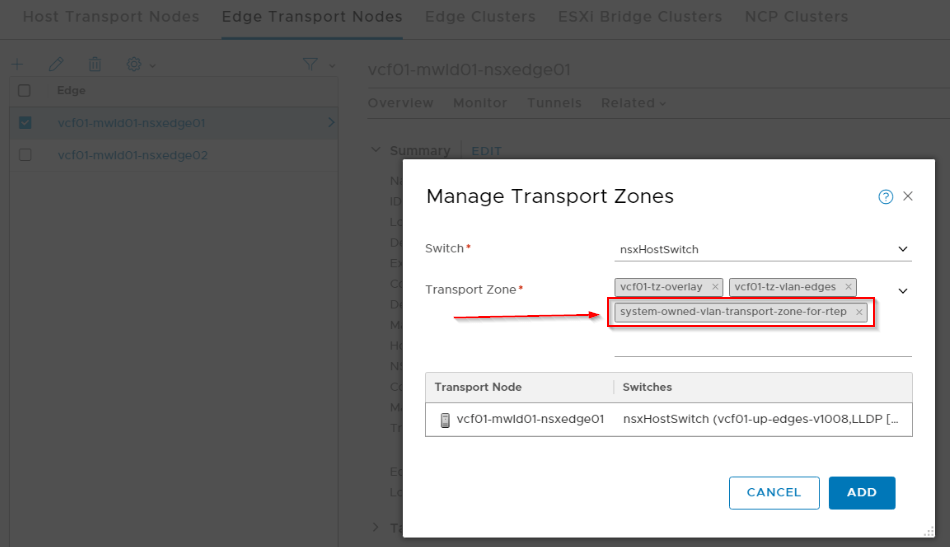
RTEP configuration will add an internal VLAN Transport zone to the edge nodes.
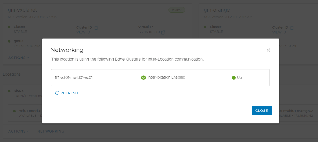
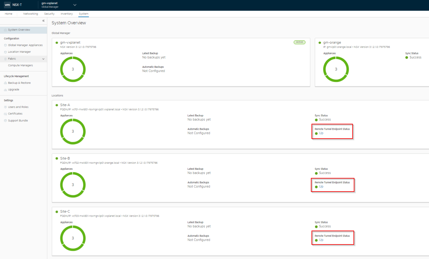
Now verify that all the sites have RTEP enabled on the edge cluster.
Each Edge in a site establishes a full mesh geneve tunnel with edges in other locations over the RTEP interface.
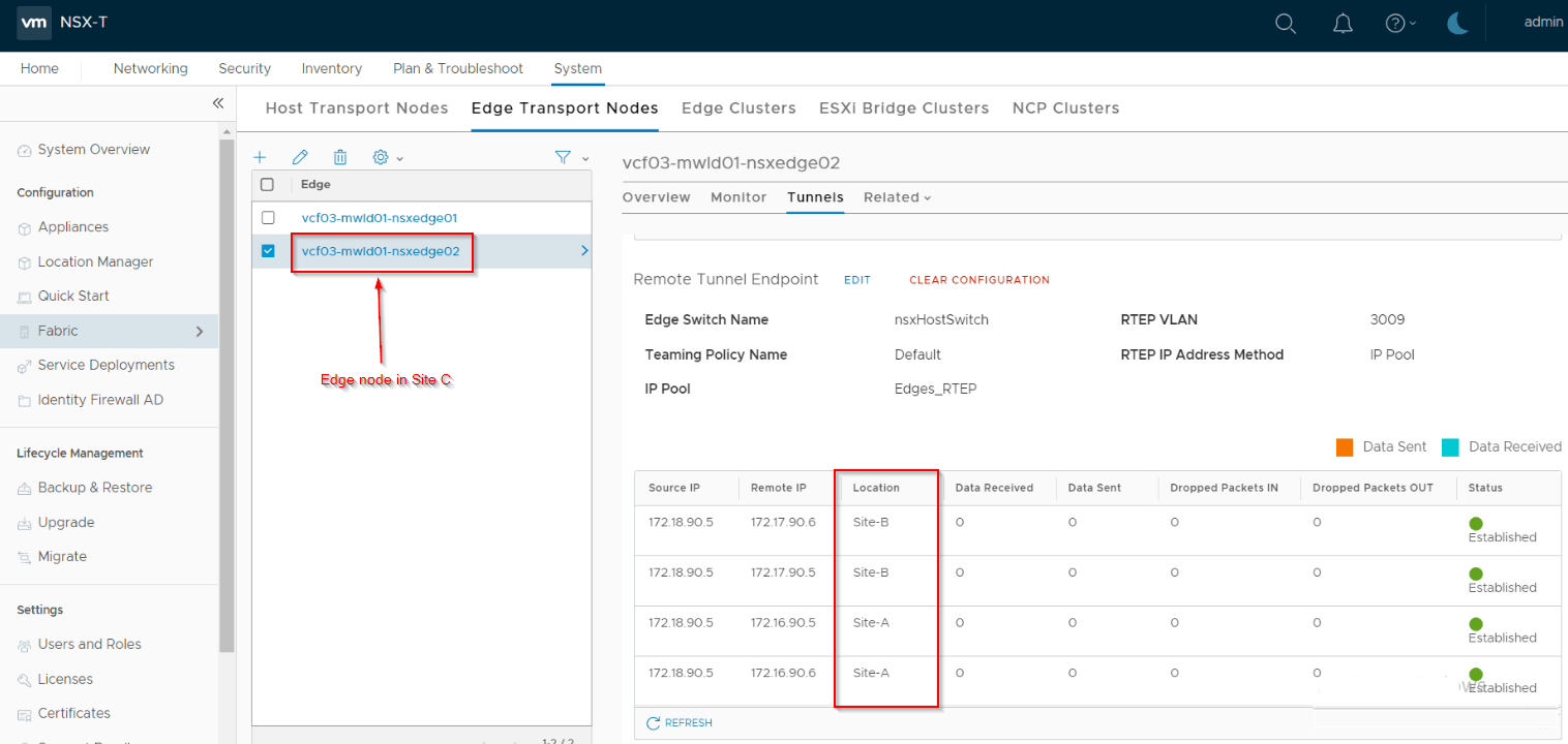
The RTEP interfaces are configured on a separate VRF and a full mesh iBGP peering is established over this VRF with the remote sites.


That’s all for this article. We will continue with other federation topics in the subsequent articles where we discuss about stretched networking, control plane and multisite routing. Stay tuned.
I hope the article was informative.
Thanks for reading.
Continue reading? Here are the other parts of this series:
Part 8 : https://vxplanet.com/2021/06/02/nsx-t-federation-part-8-tier-1-gateway-placement-considerations/
Part 9 : https://vxplanet.com/2021/06/09/nsx-t-federation-part-9-federation-control-plane-explained/
Part 11 : https://vxplanet.com/2021/06/20/nsx-t-federation-part-11-site-failures-and-network-recovery/
