

Welcome to Part 8 of the blog series on NSX-T federation. In the previous articles, we have gone through the configuration of different stretched Tier 0 Gateway topologies and explanation of north-south and east-west traffic patterns including packet walks. Now let’s take a look at how the traffic patterns are influenced by the placement of Tier 1 gateways.
As discussed earlier, we have the below deployment options for a Tier 1 gateway:
- Stretched Tier 1 gateway with no services (DR only)
- Stretched Tier 1 gateway with services (with SR)
- Non-stretched Tier 1 gateway with services (with SR)
The span of the Tier 1 gateway depends on the span of the Tier 0 gateway to which it is attached to. To have a custom span for Tier 1 gateway, it has to be instantiated in a edge cluster. Note that the span of a Tier 1 gateway cannot exceed the span of it’s upstream T0 gateway.
- T1 gateway with DR only has a span equal to it’s upstream T0 gateway
- T1 gateway with SR has a custom span equal to or less than the span of the upstream gateway
- Non-stretched T1 gateway (with SR) has a span within a specific location only.
Note that we can’t have a non-stretched T1 gateway with a DR only option. To achieve this, the T1 gateway need to be created from the local manager. But this wont be visible to the global manager.
Now let’s get started:
Northbound from Stretched T1 Gateway – DR only on stretched Active-Standby T0 gateway with location Primary-Secondary
For the Primary location:
- For a northbound flow from a segment attached to the stretched Tier 1 Gateway (DR only), the T1 DR lookup happens locally on the ESXi transport node.
- T0 DR lookup also happens locally on the ESXi transport node.
- For the T0 SR lookup, traffic will be tunnelled (using TEP interfaces) to the Active Edge node (Primary location) from where it will egress out over it’s two T0 uplinks.
For the Secondary location:
- T1 DR lookup happens locally on the ESXi transport node
- T0 DR lookup also happens locally on the ESXi transport node.
- For the T0 SR lookup, traffic will be tunnelled (using TEP interfaces) to the Active Edge node (Secondary location). Secondary location edge nodes will next-hop to the Active edge node on the primary location.
- Traffic will be tunnelled again (using RTEP interfaces) from the secondary location edge node to primary location active edge node
- Traffic will egress through the two T0 uplinks of the active edge node in the primary location.
The below sketch depicts the northbound flow:

Northbound from Stretched T1 Gateway – DR only on stretched Active-Active T0 gateway with location Primary-Secondary
For the Primary location:
- For a northbound flow from a segment attached to the stretched Tier 1 Gateway (DR only), the T1 DR lookup happens locally on the ESXi transport node.
- T0 DR lookup also happens locally on the ESXi transport node.
- For the T0 SR lookup, traffic will be tunnelled (using TEP interfaces) to one of the Active Edge nodes in the primary location (T0 DR to SR ECMP) from where it will egress out over it’s two T0 uplinks.
- Remember that from the ESXi transport nodes to the edges, we have Tier 0 DR to SR ECMP northbound. This ECMP is scalable.
For the Secondary location:
- T1 DR lookup happens locally on the ESXi transport node
- T0 DR lookup also happens locally on the ESXi transport node.
- For the T0 SR lookup, traffic will be tunnelled (using TEP interfaces) to one of the Active Edge nodes in the secondary location (T0 DR to SR ECMP). Secondary location edge nodes will next-hop to both of the Active edge nodes on the primary location (except for location specific prefixes)
- Traffic will be tunnelled again (using RTEP interfaces) from the secondary location edge node to primary location edge node (ECMP).
- Traffic will egress through the two T0 uplinks of the edge node in the primary location.
The below sketch depicts the northbound flow:

Northbound from Stretched T1 Gateway – DR only on stretched Active-Active T0 gateway with location All-Primary
- For a northbound flow from a segment attached to the stretched Tier 1 Gateway (DR only), the T1 DR lookup happens locally on the ESXi transport node.
- T0 DR lookup also happens locally on the ESXi transport node.
- For the T0 SR lookup, traffic will be tunnelled (using TEP interfaces) to one of the Active Edge nodes in the same location (T0 DR to SR ECMP) from where it will egress out over it’s two T0 uplinks. Each location has local egress to their respective Leaf switches.
- Remember that from the ESXi transport nodes to the edges, we have Tier 0 DR to SR ECMP northbound. This ECMP is scalable.
The below sketch depicts the flow from Site A & B:

Northbound from Stretched T1 Gateway with SR primary co-located with stretched Active-Active T0 gateway’s primary location in Primary-Secondary topology
For the Primary location:
- For a northbound flow from a segment attached to the stretched Tier 1 Gateway with SR construct, the T1 DR lookup happens locally on the ESXi transport node.
- To reach T1 SR , traffic is tunnelled (TEP interfaces) to the Active edge node (for T1) of the primary location.
- T0 DR lookup happens locally on the edge node in the primary location.
- T0 SR lookup also happens locally on the edge node and will egress out over it’s two T0 uplink interfaces. Note that only one edge node (the active node of T1) is involved in northbound routing.
For the Secondary location:
- T1 DR lookup happens locally on the ESXi transport node
- To reach T1 SR , traffic is tunnelled (TEP interfaces) to the Active edge node (for T1) of the secondary location.
- Since the T1 SR primary location is co-located with the T0 primary site, traffic will be RTEP tunnelled to primary location’s active edge node for T1 SR.
- T0 DR lookup happens locally on the primary location’s active edge node (for T1 SR).
- T0 SR lookup also happens locally on the same edge node on the primary location and will egress out over it’s two T0 uplink interfaces. Note that only one edge node (the active node of T1) is involved in northbound routing in this case as well.
The below sketch depicts the northbound flow:

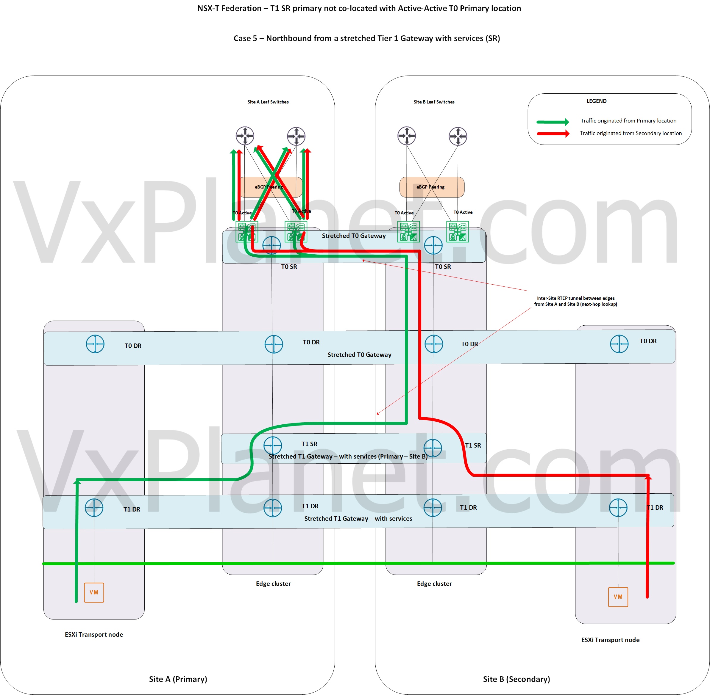
Northbound from Stretched T1 Gateway with SR primary NOT co-located with stretched Active-Active T0 gateway’s primary location in Primary-Secondary topology
For the Primary location:
- For a northbound flow from a segment attached to the stretched Tier 1 Gateway with SR construct, the T1 DR lookup happens locally on the ESXi transport node.
- To reach T1 SR , traffic is tunnelled (TEP interfaces) to the Active edge node (for T1) of the primary location.
- Since the T1 SR primary location is on Site B (T0 secondary), traffic will be RTEP tunnelled to Site B’s active edge node for T1 SR.
- T0 DR lookup happens locally on Site B’s active edge node (for T1 SR).
- T0 SR lookup also happens locally on this edge node from where it will be tunnelled (RTEP) back to Site A (primary location) for egress (with ECMP)
- Notice a traffic hair pinning scenario here.
For the Secondary location:
- T1 DR lookup happens locally on the ESXi transport node
- To reach T1 SR , traffic is tunnelled (TEP interfaces) to the Active edge node (for T1) of the secondary location.
- T0 DR lookup happens locally on the edge node in the secondary location.
- T0 SR lookup also happens locally on this edge node from where it will be tunnelled (RTEP) back to Site A (primary location) for egress (with ECMP)
The below sketch depicts the northbound flow:
Northbound from Stretched T1 Gateway with SR primary on Site A on stretched Active-Active T0 gateway with location All-Primary
Primary location Site A
- For a northbound flow from a segment attached to the stretched Tier 1 Gateway in Site A, the T1 DR lookup happens locally on the ESXi transport node.
- To reach T1 SR , traffic is tunnelled (TEP interfaces) to the Active edge node (for T1) in the same location, Site A
- T0 DR lookup happens locally on Site A’s T1 active edge node.
- T0 SR lookup also happens locally on the same edge node in Site A and will egress out over it’s two T0 uplink interfaces. Note that only one edge node (the active node of T1) is involved in northbound routing in this case.
Primary location Site B
- For a northbound flow from a segment attached to the stretched Tier 1 Gateway in Site B, the T1 DR lookup happens locally on the ESXi transport node.
- To reach T1 SR , traffic is tunnelled (TEP interfaces) to the Active edge node (for T1) in the same location, Site B
- Since the T1 SR primary location is Site A, traffic will be RTEP tunnelled to Site A’s active edge node for T1 SR.
- T0 DR lookup happens locally on Site A’s active edge node (for T1 SR).
- T0 SR lookup also happens locally on the same edge node in Site A and will egress out over it’s two T0 uplink interfaces. Note that only one edge node (the active node of T1) is involved in northbound routing in this case.
- In this case, the egress to customer networks happens on Site A and not locally on Site B.

Northbound from Non-stretched T1 Gateway (with SR) on stretched Active-Active T0 Gateway with location Primary-Secondary
For the Primary site:
- T1 DR lookup happens locally on the ESXi transport node.
- For T1 SR lookup, traffic is tunnelled to the active edge node of the primary location (for T1)
- T0 DR lookup happens locally on the T1 SR active edge node.
- T0 SR lookup also happens locally on this edge node and the traffic egresses via the T0 uplinks. Note that only one edge node (the active node of T1) is involved in northbound routing.
For the Secondary site:
- T1 DR lookup happens locally on the ESXi transport nodes.
- For T1 SR lookup, traffic is tunnelled to the active edge node of the secondary location (for T1).
- T0 DR lookup happens locally on the active edge node of the secondary location.
- T0 SR lookup also happens locally on this edge node from where it will be tunnelled (RTEP) to primary location for egress (with ECMP)
The below sketch depicts the northbound flow:

Northbound from Non-stretched T1 Gateway (with SR) on stretched Active-Active T0 Gateway with location All-Primary
- For a northbound flow from a segment attached to the non-stretched Tier 1 Gateway with SR, the T1 DR lookup happens locally on the ESXi transport node.
- To reach T1 SR , traffic is tunnelled (TEP interfaces) to the Active edge node (for T1) on the same location.
- T0 DR lookup happens locally on the edge node in the same location.
- T0 SR lookup also happens locally on the edge node and will egress out locally over it’s two T0 uplink interfaces. Note that only one edge node (the active node of T1) is involved in northbound routing.
- We have local egress per location.

East-West between VMs on stretched DR-only T1 gateways within a host
East-West traffic patterns are almost identical for all the stretched T0 gateway deployment topologies because T0 SR construct is not involved in East-West flows.
Assuming the ESXi host is in the secondary location,
- For a segment attached to stretched T1 gateway with DR only, T1 DR lookup happens locally on the ESXi host.
- T0 DR lookup also happens locally on the same ESXi host.
- DR lookup of the destination T1 Gateway (DR only) also happens locally on the same ESXi host.
- Traffic stays within the ESXi host for the end to end communication.

East-West between VMs on non-stretched T1 gateway (with SR) and stretched T1 gateway – DR only within a host
Assuming the ESXi host is in the secondary location,
- For a segment attached to non-stretched T1 gateway with SR, T1 DR lookup happens locally on the ESXi host.
- For the T1 SR lookup, traffic is tunnelled to the T1 Active edge node on the same location.
- T0 DR lookup happens locally on the same edge node.
- DR lookup of the destination T1 Gateway (DR only) also happens locally on the same edge node.
- Traffic will be tunnelled form the edge node to ESXi host to reach the destination VM.
- Return traffic pattern can be different as routing always happens closer to the source.
- Note that traffic had to leave the ESXi host and get routed over the edge node as T1 SR construct was involved in the data path.

East-West between VMs on stretched T1 gateway with and without SR within a host
Assuming the ESXi host is in the secondary location,
- For a segment attached to stretched T1 gateway with SR, T1 DR lookup happens locally in the ESXi host.
- T1 SR lookup happens on the T1 Active edge node in the same secondary location.
- Traffic is RTEP tunnelled to the T1 SR Active edge node in the primary location as the next hop of T1 SR on secondary points to primary location for further routing lookups.
- T0 DR lookup happens on the edge node on the primary location.
- DR lookup of the destination T1 Gateway (DR only) also happen locally on the edge node in the primary location.
- Traffic will be RTEP tunnelled back to the edge node of the secondary location from where it gets TEP tunnelled to the destination ESXi host to reach the destination VM.
- Note that traffic had to cross to the primary location inorder to complete the T1 SR lookup on the primary location.

East-West between VMs on stretched and non-stretched T1 gateways with SR within a host
Similar to the previous scenario, traffic has to cross to the primary location inorder to complete the SR lookup of stretched T1 gateway.

Stretched T1 Gateway on a dedicated edge cluster
Having the stretched T1 gateway with SR on a dedicated edge cluster will influence the northbound routing and gives more northbound ECMP paths. This is being dealt as a separate article in Part 10.
Part 10 : https://vxplanet.com/2021/06/17/nsx-t-federation-part-10-dedicated-edge-cluster-for-stretched-tier-1-gateways/
T1 gateway placement considerations
- Stretched T1 gateway – DR only has the shortest lookups with no hairpinning. If source-destination VMs are on the same ESXi host, traffic stays local to the host as much as possible.
- Non-stretched T1 gateway with SR introduces edge node to the data path. If the communication is between non-stretched T1 gateway (with SR) to another non-stretched T1 gateway (with SR) or to stretched DR only T1 gateway, traffic stays local to the location.
- If we introduce a stretched T1 gateway with SR, it requires a primary location for the T1 SR. As such, we introduce this primary location as the next-hop in the data path.
- Placement of T1 SR Primary location is important to avoid hairpinning of traffic between locations. In most cases, we co-locate T1 SR primary location with it’s upstream T0 primary location.
- In a stretched Active-Active T0 All-Primary topology, local egress is influenced if the data path encounters a stretched T1 SR with primary on different location.
- Having a T1 SR construct on a shared T0 and T1 edge cluster influences the number of ECMP paths northbound. Traffic always egress locally form the edge node (strictly local forwarding)
- Having a dedicated edge cluster for stretched T1 gateway gives more northbound ECMP options.
Time to wrap up!!! This has been a time consuming article, and I hope it was informative and you bookmark it.
Will meet in next article where we discuss about the Federation control plane.
Thanks for reading
Continue reading? Here are the other parts of this series:
Part 1 : https://vxplanet.com/2021/04/13/nsx-t-federation-part-1-onboarding/
Part 9 : https://vxplanet.com/2021/06/09/nsx-t-federation-part-9-federation-control-plane-explained/
Part 11 : https://vxplanet.com/2021/06/20/nsx-t-federation-part-11-site-failures-and-network-recovery/
