

This is Part 2 of the blog series on NSX-T Federation and we will discuss about stretched networking configuration and routing. We will start with the explanation and configuration of a stretched Active / Standby Tier 0 Gateway with location primary / Secondary.
If you missed Part 1 where we discussed about the onboarding process, you can read it below:
Part 1 : https://vxplanet.com/2021/04/13/nsx-t-federation-part-1-onboarding/
With NSX-T federation, we have the concept of stretched networking where the networking objects stretch across locations based on the defined span. We can stretch Tier 0 Gateways, Tier 1 Gateways (with and without SR) and logical segments. NSX-T GM maintains an Asynchronous Replication (AR) channel which has queues for each location where the configuration objects are being pushed to. Each location is a consumer to it’s queue on the GM and once the configuration item is consumed, the LM provisions the objects locally. Since it is the responsibility of LM to provision the location specific objects, a stretched logical segment can have different VNIs across locations. For eg, a stretched segment can have a VNI of 12001 in Site A , VNI of 13001 in Site B and VNI of 14001 in Site C but still on the same L2 domain. The Edge RTEPs (Active L2forwarders) glues together the VNIs of locations together through RTEP-RTEP internal tunnel VNIs.
Below are few important things to be noted while configuring stretched networking:
- The stretch of an object is defined by it’s configured span. If a Gateway is stretched only to location A & B, location C will never get the configuration item through the AR queue and will not realize those objects.
- Locations can be Primary or Secondary based on how we want the Ingress / Egress point.
- In Primary / secondary location based deployment, primary will be the egress location and we achieve what is called ‘Centralized Egress’. Ingress to NSX-T is not fully controlled by the NSX-T routing configuration
- In ‘All Primary’ location based deployment, all sites have egress capability. This is called ‘Per-location Local Egress’. Ingress routing is controlled outside of NSX-T and we mostly deal with assymetric routing in this scenario.
- In a Primary / Secondary deployment, the priority of the secondary sites determines who takes over the primary role in case the primary location goes down. Switching over the primary role is currently a manual process.
- Below are the valid Tier 0 Gateway deployment topologies:
- Active / Standby Tier 0 with location Primary / Secondary
- Active / Active Tier 0 Gateway with location Primary / Secondary
- Active / Active Tier 0 Gateway with location All Primary
- The span of a Tier 1 Gateway is decided by the span of the Tier 0 Gateway to which it is attached to UNLESS the Tier 1 is instantiated within an edge cluster.
- A DR-only Tier 1 has a span equal to it’s upstream Tier 0 span
- A Tier 1 with services (edge cluster) has a custom span and is always deployed in Active / Standby with location Primary / Secondary
- In most cases, the Tier 1 (with services) primary location follows Tier 0 primary location to avoid suboptimal routing.
- The span of a logical segment is defined by the span of the logical gateway to which it is attached to.
- A downstream gateway (eg: T1 with SR) can’t have a span greater than it upstream gateway (T0 Gateway)
- If a segment isn’t attached to a gateway, then it doesn’t have any span. It remains as a configuration item on the GM and is not pushed to the LMs.
- If the T0 Gateway is not stretched, then all downstream objects are also unstretched.
- All stretched objects are created from the GM. Any objects created on the LM won’t be synced back to the GM (except during initial import)
Now let’s get started:
Our Topology
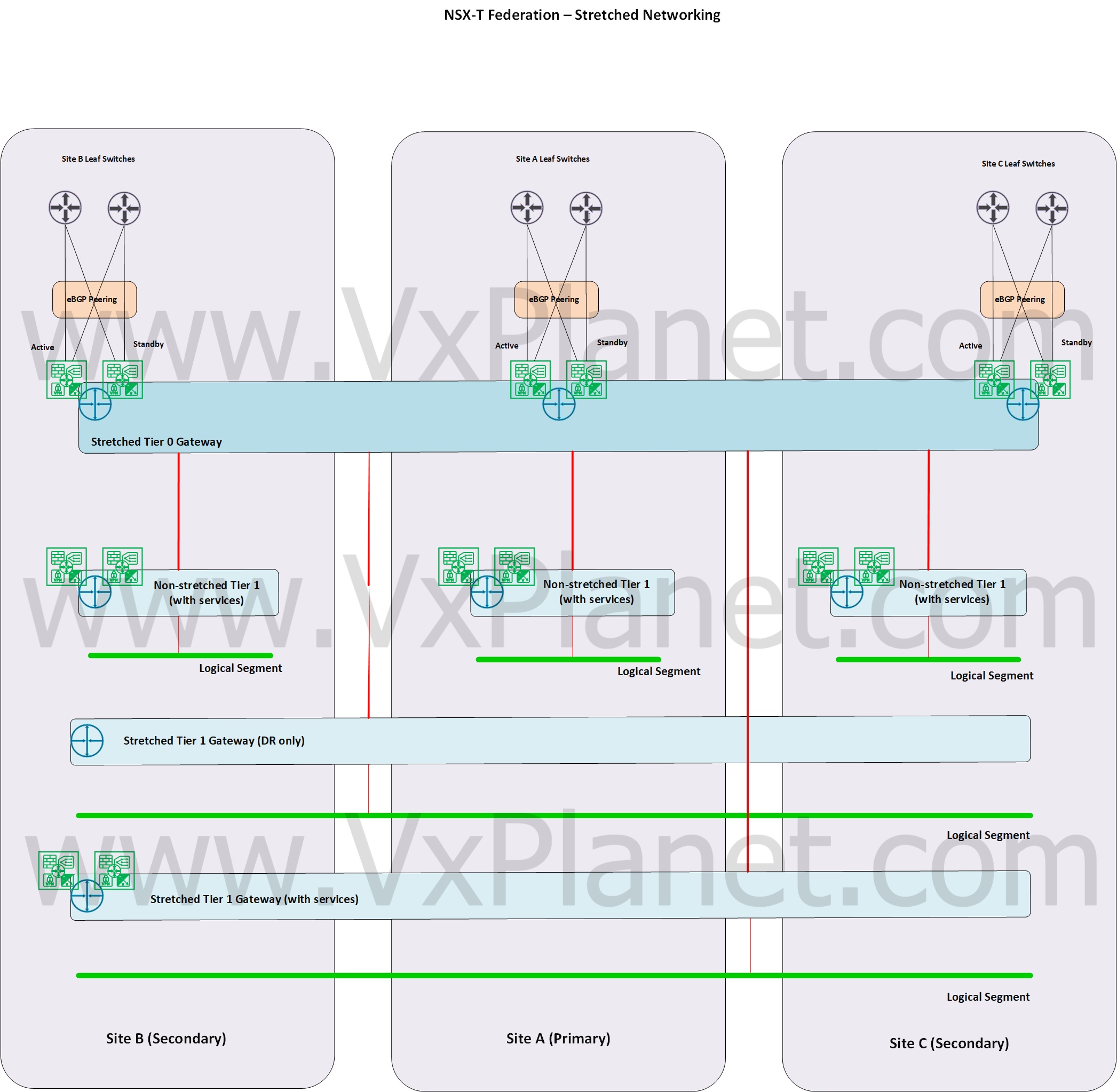
Below is the topology we are going to build in this article. We have a stretched Active / Standby Tier 0 Gateway spanned across the three locations – Site A, Site B and Site C. Site A is Primary and all others Secondary. Site B has a higher priority and takes over the primary role when the primary location goes down.
We have 5 Tier 1 Gateways downstream:
- Stretched Tier 1 Gateway with DR only.
- Stretched Tier 1 Gateway with SR (instantiated in an edge cluster)
- Unstretched Tier 1 Gateway in site A only (globally provisioned)
- Unstretched Tier 1 Gateway in site B only (globally provisioned)
- Unstretched Tier 1 Gateway in site C only (globally provisioned)
For each Tier 1 deployment model, the northbound / southbound traffic directions are different. We will take a look at that in the Packet Walk article coming up next (Part 3)
We have 5 stretched logical segments each attached to separate stretched Tier 1 gateways:
- Segment attached to stretched Tier 1 gateway with DR only (192.168.101.0/24)
- Segment attached to stretched Tier 1 gateway with SR (192.168.102.0/24)
- Segment attached to Tier 1 gateway in site A only (192.168.103.0/24)
- Segment attached to Tier 1 gateway in site B only (192.168.104.0/24)
- Segment attached to Tier 1 gateway in site C only (192.168.105.0/24)
Configuring Stretched Tier 0 Gateway
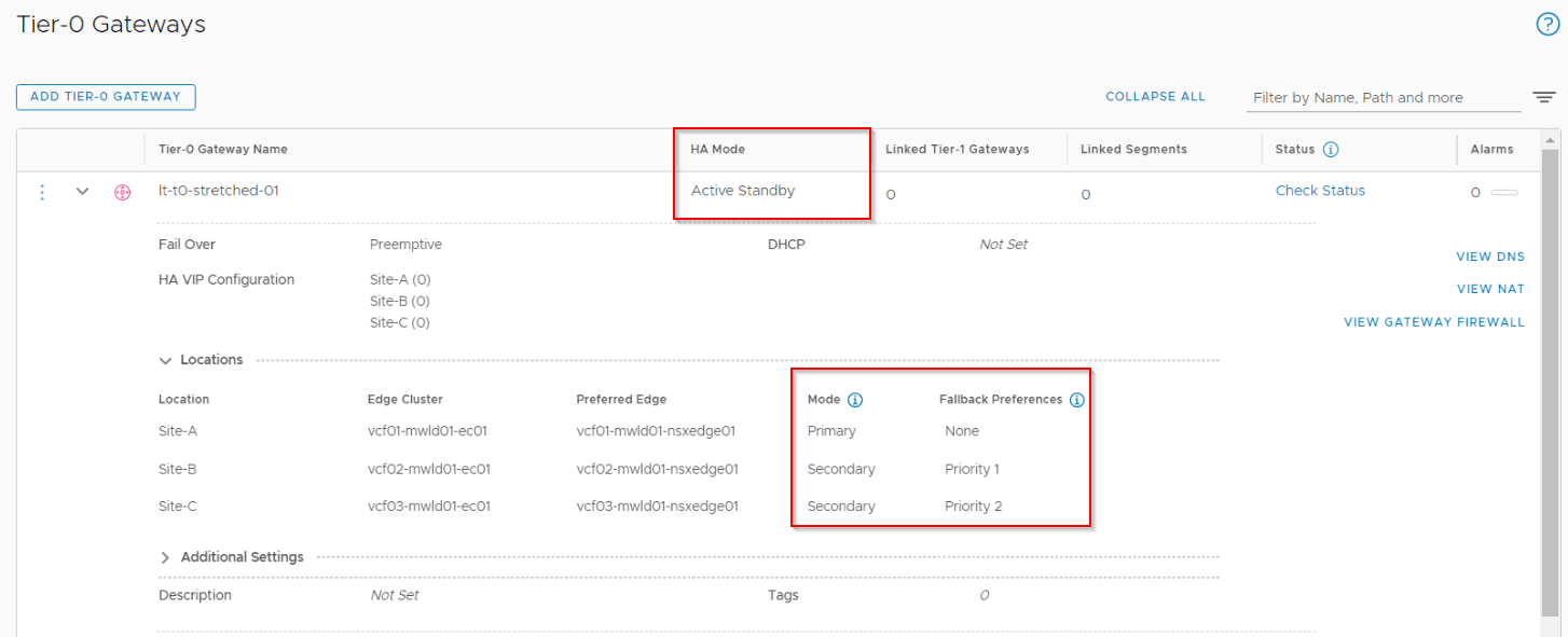
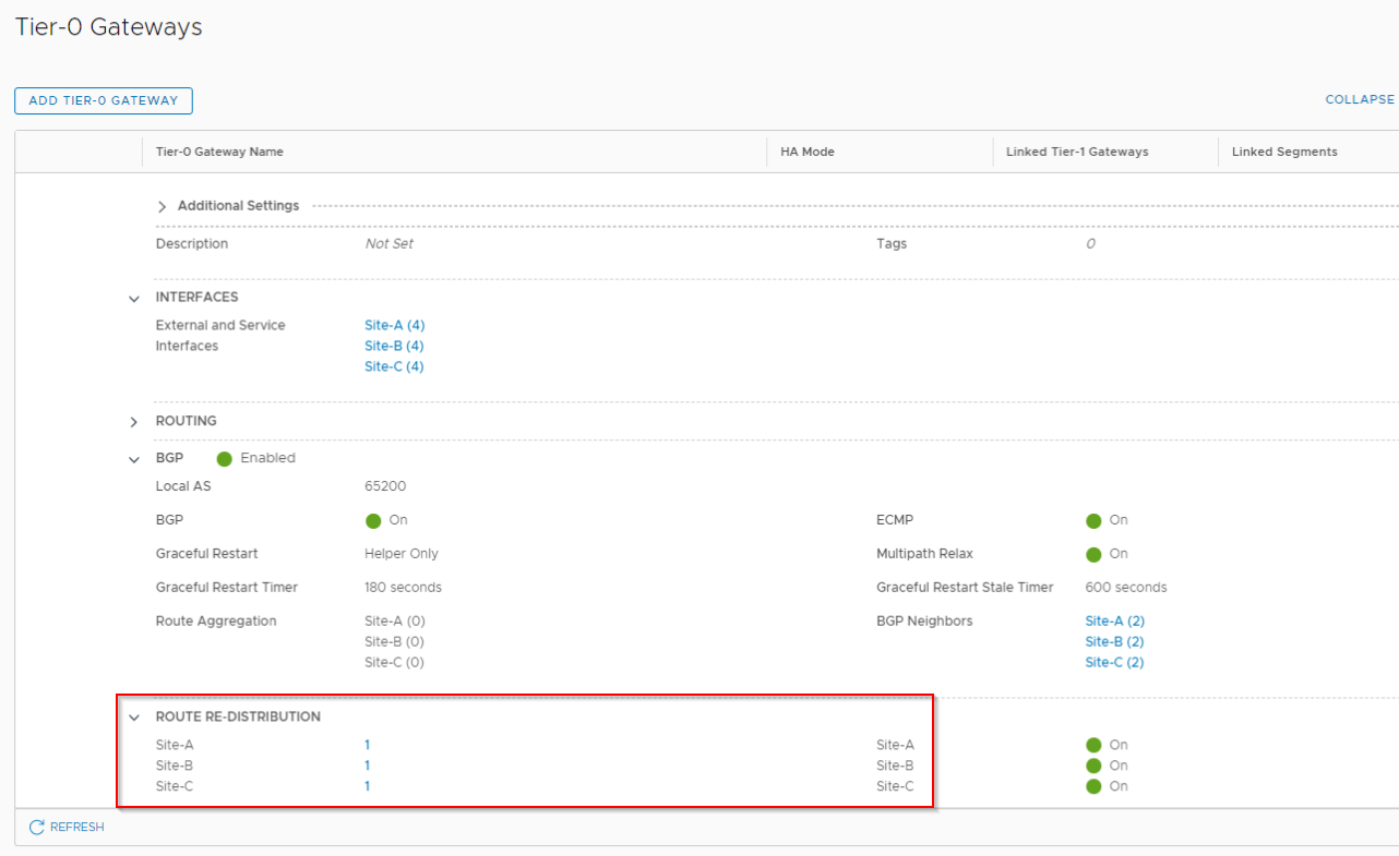
Tier 0 Gateway is deployed in Active / Standby form with location spanned to Site A, Site B and Site C. Site A is the primary location and the secondary site, Site B has the highest priority to take over the primary role when Site A goes down.
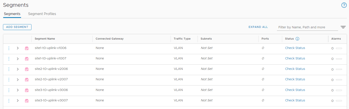
We require Edge T0 uplink VLAN logical segments for each location. Based on the VLAN schema in Part 1, we configure 2 VLAN logical segments per site, and a total of 6 VLAN logical segments. VLAN Transport zones for edges need to be created on the LMs directly.
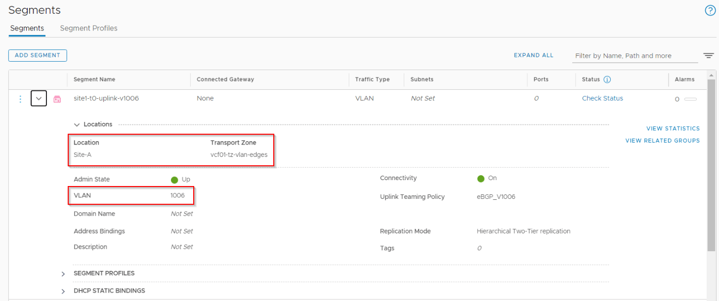
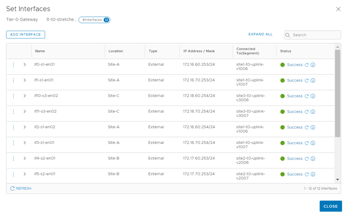
Each site will have 4 T0 interfaces – two via edge node 1 on VLAN X and 2 via edge node on VLAN Y. This makes a total of 12 T0 interfaces on the stretched T0 gateway. IP Address are chosen form the VLAN / IP schema defined in Part 1. Each T0 interface also has a span, so an interface created on Site A will not be realized on Site B and Site C.
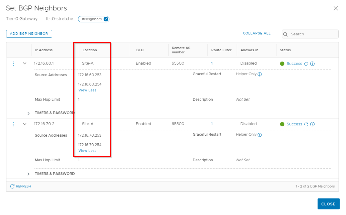
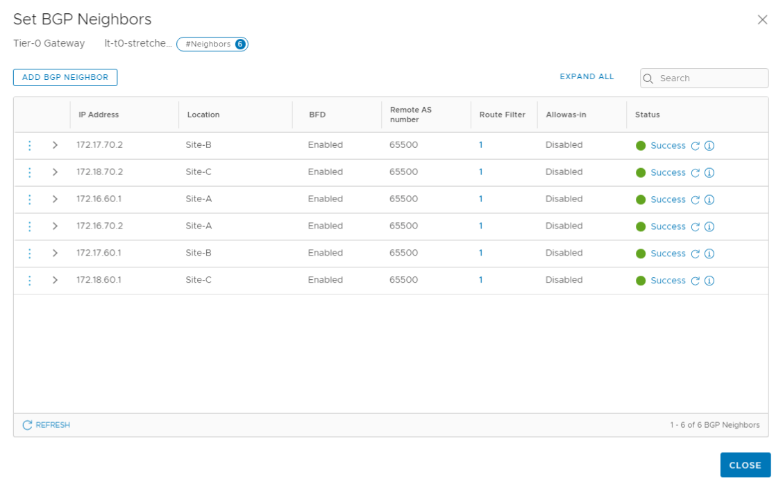
BGP neighborship from the T0 interfaces with the Leaf switches are established on a location basis. Note that this stretched T0 has a single ASN 65200 across locations.
Finally set route redistribution criteria, this also has a span.
Configuring Stretched Tier 1 Gateways
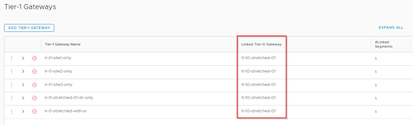
As mentioned earlier, we will configure five stretched Tier 1 Gateway upstreamed to the above Tier 0 stretched gateway
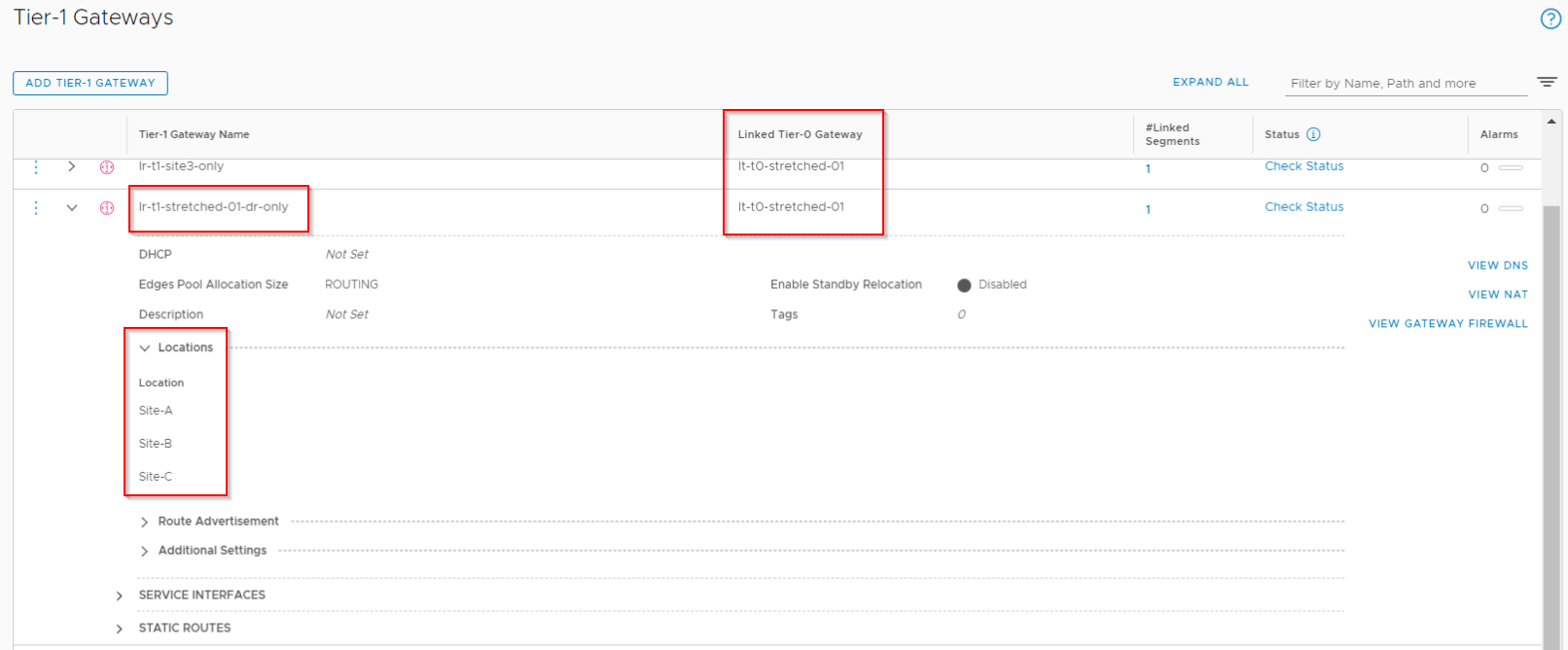
- Stretched Tier 1 Gateway with DR only – (lr-t1-stretched-01-dr-only)
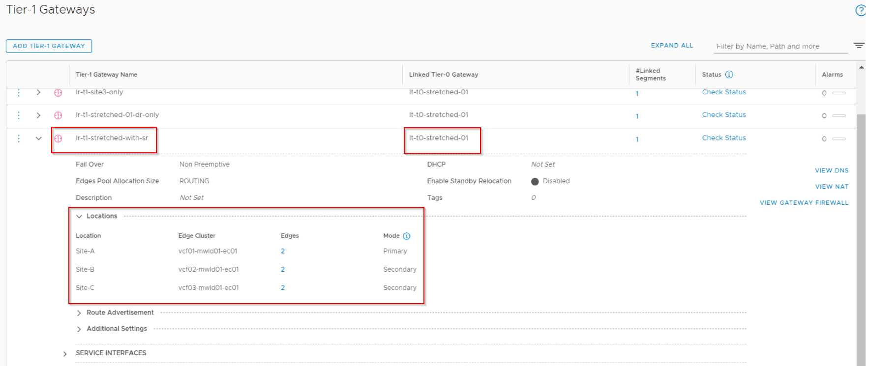
- Stretched Tier 1 Gateway with SR (instantiated in an edge cluster) – (lr-t1-stretched-with-sr)
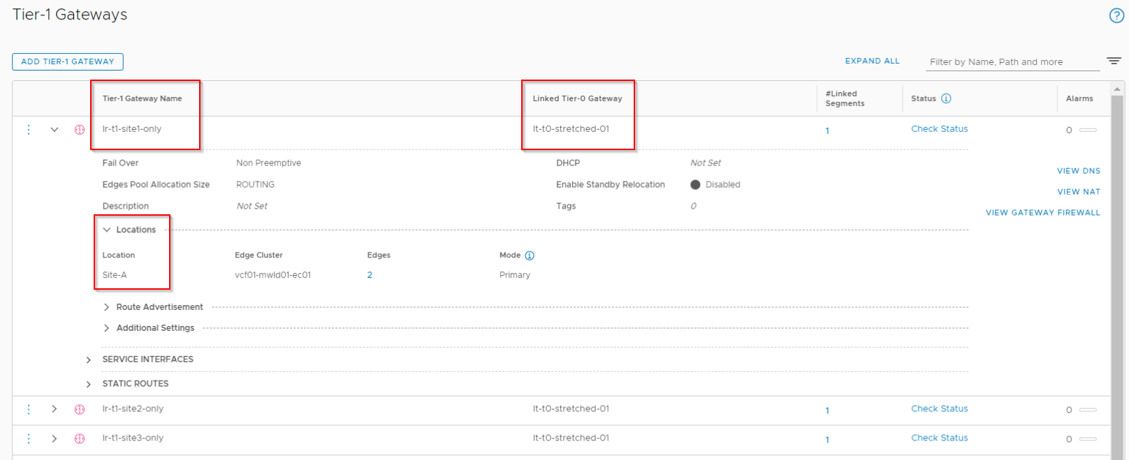
- Tier 1 Gateway in site A only (globally provisioned) – (lr-t1-site1-only)
- Tier 1 Gateway in site B only (globally provisioned) – (lr-t1-site2-only)
- Tier 1 Gateway in site C only (globally provisioned) – (lr-t1-site3-only)
DR-only T1 follows the stretched T0 Gateway’s span.
T1 with SR (services) will be instantiated in an edge cluster and the span is configured manually (can have a custom span). This T1 Gateway is Active / Standby with Site A as the primary location. In most cases, T1 primary location follows the upstream T0 primary location to avoid suboptimal routing.
Site specific T1 gateways will have a span of local location only.
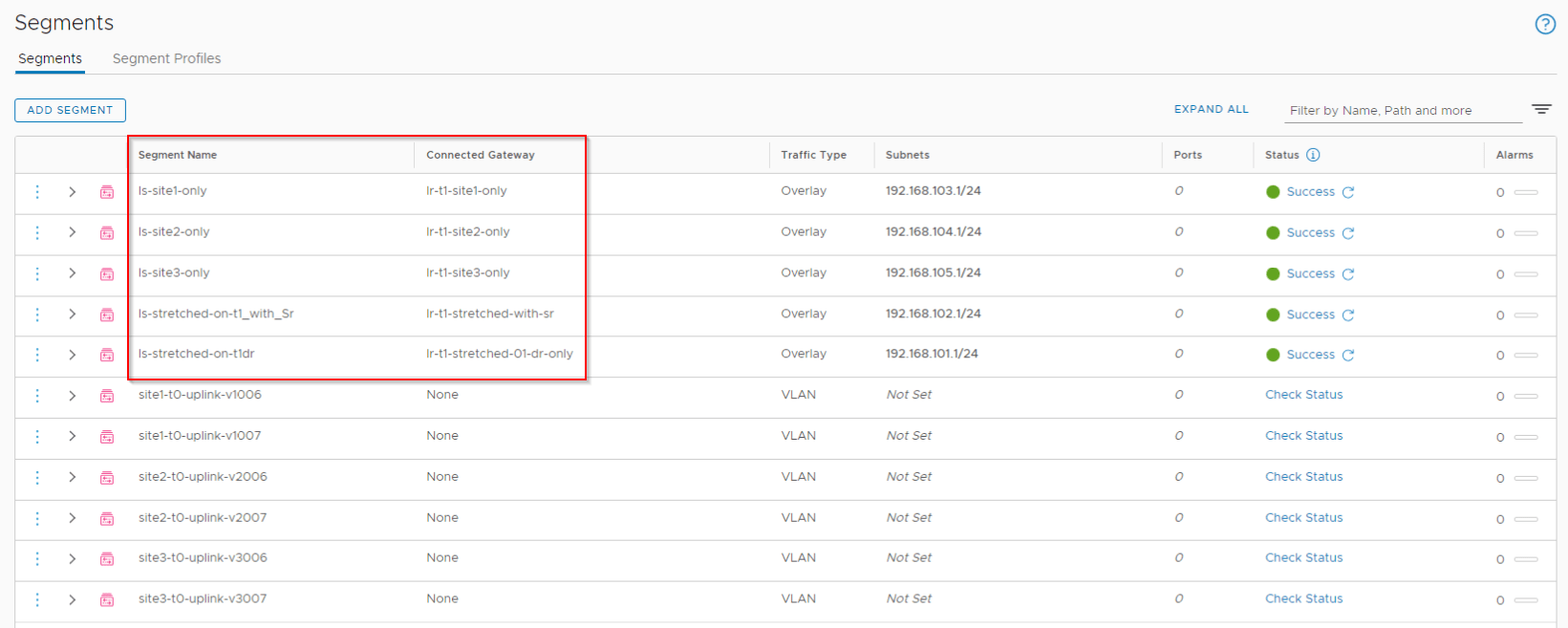
Configuring stretched segments
We will configure five stretched logical segments each attached to separate stretched Tier 1 gateways.
- Segment attached to stretched Tier 1 gateway with DR only (192.168.101.0/24) – ‘ls-stretched-on-t1dr’
- Segment attached to stretched Tier 1 gateway with SR (192.168.102.0/24) – ‘ls-stretched-on-t1_with_sr’
- Segment attached to Tier 1 gateway in site A only (192.168.103.0/24) – ‘ls-site1-only’
- Segment attached to Tier 1 gateway in site B only (192.168.104.0/24) – ‘ls-site2-only’
- Segment attached to Tier 1 gateway in site C only (192.168.105.0/24) – ‘ls-site3-only’
North – South routing
Primary Site
- In this topology with A/S Tier 0 Gateway with P/S location, only the primary site is involved in north-south routing with the external Leaf switches.
- Only the primary site edge nodes will advertise prefixes via BGP to the Leaf switches.
- Only the active edge node in the primary site is involved in N-S routing (reduced ECMP paths)
- Within the primary site, the Standby edge node uses as-path prepending for the advertised routes that makes it less preferable for the south bound traffic to the T0 gateway.
- The primary site advertises subnets from all locations. This includes both local subnets (Site A subnets – local + stretched) as well as remote subnets (Site B and Site C local + stretched subnets)
- Only the primary site edges receives and learns routes over BGP from the Leaf switches.
- With inter-SR routing, all primary site prefixes are advertised to the secondary sites through a full mesh iBGP relationship.
- When the primary site fails, with a manual intervention the secondary site with highest priority takes over and does the centralized N-S egress.
Secondary Sites
- Secondary sites successfully establishes eBGP relationship with the Leafs but they DO NOT advertise or learn routes from the Leafs
- The forwarding table on the secondary site edge nodes has a next hop pointing to the primary site’s active edge node, hence all the northbound traffic is forwarded to the primary site.
- With Inter-SR routing, all secondary locations learn the customer networks via the primary site. Inter-SR learned routes are given more preference than locally learned routes while building the forwarding table.
- Within the secondary site, only the active edge node is involved in forwarding traffic to the primary site.
Inter-SR routing
There is a full mesh inter-SR iBGP routing between the edge nodes across locations (inter-site). Since the T0 deployment mode per location is Active / Standby, there is NO inter-SR iBGP between edges within the location (intra-site). The subnet 169.254.32.X/20 is used for inter-SR iBGP
The primary site establishes eBGP peering with the Leaf switches over the default VRF. Inter-SR routing happens over a separate internal VRF (inter_sr_vrf). All learned prefixes are leaked from the default VRF into the Inter-SR VRF where a full mesh iBGP is set up between edges across locations. All secondary locations learn the customer prefixes via inter-SR iBGP with next-hop set to primary location. On all secondaries, the inter-SR learned prefixes are given higher preference than the prefixes in the default VRF and the forwarding table is updated accordingly.
For more details on inter-SR routing in NSX-T 3.0, check out my previous article here: https://vxplanet.com/2020/09/12/tier-0-inter-sr-routing-changes-in-nsx-t-3-0/
Let’s have a look at this in more detail.
As discussed above, Leaf switches receives prefixes only from the primary site.

The standby edge node on the primary site does as-path prepending for the routes advertised to the Leafs making it less preferable.

None of the secondary sites will advertise prefixes to the Leafs.

The ingress point to the NSX-T tenants is only via the primary site and that over the active edge node.


Inter-SR iBGP is enabled between edges across locations. Since the T0 deployment mode is Active / Standby, no inter-SR iBGP between edges intra-site.

This is the Inter-SR iBGP table from a secondary site edge node that receives all the customer prefixes via the primary site.

This is the default BGP table from the primary site active edge node that shows the next-hops to customer prefixes (Leaf switches) and to other site’s prefixes.
Prefixes 192.168.104.0/24 and 192.168.105.0/24 belongs to Site B & C respectively. The next hops are updated appropriately.

This is the forwarding table from Site B and Site C. The next-hop for northbound traffic points to Site A edge node.


The forwarding tables on standby edge nodes are also kept in sync to reduce the convergence time during edge failover.

Let’s look at the geneve tunnel interfaces created on the edge nodes for inter-SR routing on the inter_sr_vrf. An active edge node will have 2 IP addresses on the tunnel interface – one for iBGP peering and second for next-hop. The next-hop IP on the active edge node moves to the standby edge node during failover eliminating the need to update forwarding tables during edge failovers.

Let’s invoke an edge failover on one site (Site A) and confirm this.


Notice the next-hop IP 169.254.32.2 has successfully moved to the new active edge node.
Let’s wrap-up, we will continue in Part 3 to discuss the connectivity and packet walk north-south and east-west.
I hope this article was informative.
Thanks for reading
Continue reading? Here are the other parts of this series:
Part 1 : https://vxplanet.com/2021/04/13/nsx-t-federation-part-1-onboarding/
Part 8 : https://vxplanet.com/2021/06/02/nsx-t-federation-part-8-tier-1-gateway-placement-considerations/
Part 9 : https://vxplanet.com/2021/06/09/nsx-t-federation-part-9-federation-control-plane-explained/
Part 11 : https://vxplanet.com/2021/06/20/nsx-t-federation-part-11-site-failures-and-network-recovery/

Hello Hari,
First I would like to thank you for your helpful blogs,
Second, I have a question related to your TOR SWs, what kind of config is between them or to be specific the VLAN of edge uplinks are specific per TORs or you have kind of high availability between these switches.
Hi Hasan
For this blog post i used 2 ToR switches in VLT (VPC) and dedicated VLANs are used per site. In real world scenarios, edges in each site peers with the respective site’s leaf switches (BGP). It’s not mandatory to have VPC/VLT between the ToRs, just using that assuming we have other Baremetal servers (non-ESXi based) on the racks. Also be aware that using VPC/VLT without using bonding on the ESXi will also require additional considerations to handle orphan port traffic, for operations and failure scenarios. This is for an L3 Leaf-Spine architecture. For VxLAN EVPN architectures, edges peer with the VLANs under an L3VNI. Federation doesn’t support VRF currently, but in future we could map a T0 VRF with an L3VNI on the Leafs.
Thanks
Hari