

Welcome to Part 3 of the blog series on NSX-T Federation. In this article we will take a look at North-South and East-West Packet Walk for the stretched Active/Standby Tier 0 Gateway with Primary/Secondary locations which we discussed in Part 2. If you were not following along, I would recommend having a look at Part 2 before proceeding with this article:
In Part 2, we discussed that:
- Stretched Active/Standby Tier 0 Gateways can be deployed only as location Primary/Secondary. ‘All Primary’ deployment is currently not supported. This also means that we have only Centralized egress (from T0 Active edge node in primary site)
- Secondary locations won’t advertises or learn prefixes over their BGP relationship with the Leaf switches.
- There is a full mesh iBGP enabled between the inter-site edge nodes. Intra-site iBGP is not enabled as the deployment mode is T0 Active-Standby.
- T0 SR on the secondary locations will next-hop to the T0 SR of the Active edge node on the primary location.
- Only one edge node (T0 active edge) in the primary location is involved in northbound routing.
- Stretched T1 Gateways can have custom span when instantiated in an edge cluster and is always deployed as Primary-Secondary
- Introducing SR constructs for the stretched T1 Gateway will require traffic to be tunnelled to it’s primary location for routing lookups which may introduce sub-optimal paths, more on this later.
- In most cases, we co-locate stretched T1 SR primary location with the T0 primary location to avoid sub-optimal routing.
Now let’s understand the North-South and East-West traffic patterns in more detail. Note that:
- Stretched T1 DR construct is available on all the ESXi transport nodes and edge nodes (based on the span)
- Stretched T0 DR construct is available on all the ESXi transport nodes and edge nodes (based on the span)
- Stretched T1 SR construct is available only on the edge nodes (based on the span)
- Stretched T0 SR construct is available only on the edge nodes (based on the span)
- SR constructs (T0 and T1) will have a primary and secondary location. If there is an SR lookup, it needs to be routed over to it’s respective primary location for further routing lookups.
- Routing always happen closer to the source. As such southbound traffic patterns will be different from northbound patterns.
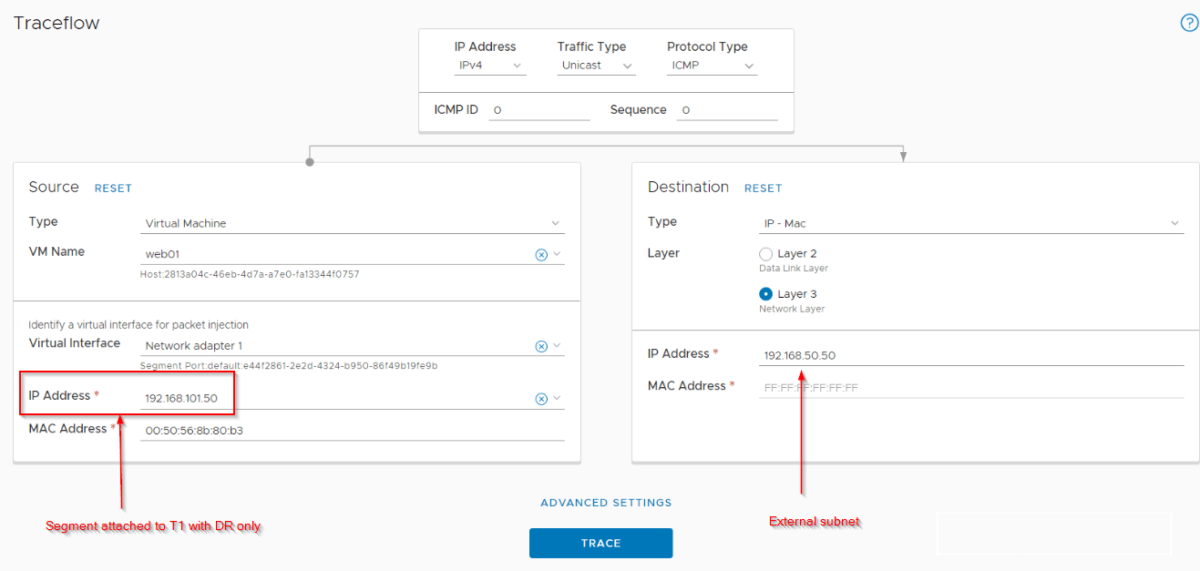
Northbound from a segment attached to stretched Tier 1 Gateway with no services (DR only)
The span of a stretched Tier 1 gateway with no services (DR only) is equal to the span of it’s upstream Tier 0 Gateway.
For the Primary location:
- For a northbound flow from a segment attached to the stretched Tier 1 Gateway (DR only), the T1 DR lookup happens locally on the ESXi transport node.
- T0 DR lookup also happens locally on the ESXi transport node.
- For the T0 SR lookup, traffic will be tunnelled (using TEP interfaces) to the Active Edge node (Primary location) from where it will egress out over it’s two T0 uplinks.
For the Secondary location:
- T1 DR lookup happens locally on the ESXi transport node
- T0 DR lookup also happens locally on the ESXi transport node.
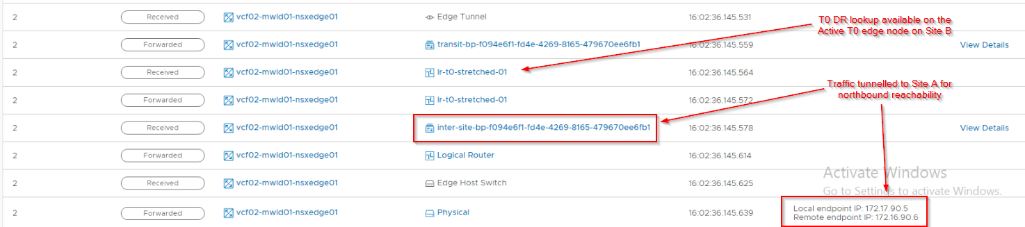
- For the T0 SR lookup, traffic will be tunnelled (using TEP interfaces) to the Active Edge node (Secondary location). Secondary location edge nodes will next-hop to the Active edge node on the primary location.
- Traffic will be tunnelled again (using RTEP interfaces) from the secondary location edge node to primary location active edge node
- Traffic will egress through the two T0 uplinks of the active edge node in the primary location.
The below sketch depicts the flow for a secondary location:

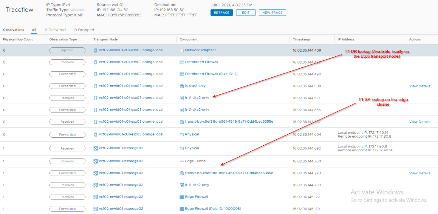
Let’s also take a look at Traceflow on the secondary location to confirm this. Note that Traceflow tool is available only on the Local managers, so we can get the flow information only on a site basis. I hope future releases will give us a multi-site traceflow visibility.
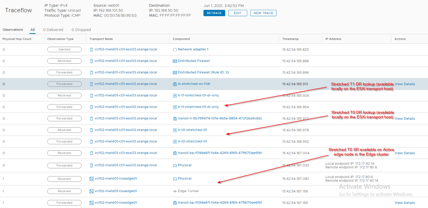
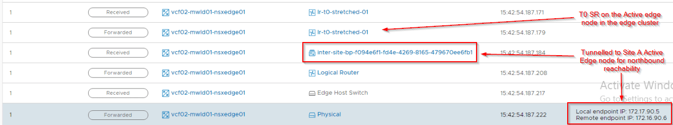
Notice that after the T0 SR lookup on the secondary location, traffic is RTEP tunnelled over to the primary location (Site A) for northbound reachability.
Northbound from a segment attached to stretched Tier 1 Gateway with services (with SR)
As discussed in Part 2, a stretched Tier 1 Gateway with services is instantiated in an edge cluster. SR construct requires Primary and secondary locations. In most cases, we co-locate stretched Tier 1 SR primary with it’s upstream stretched Tier 0 gateway’s primary location to avoid sub-optimal routing (reduce hair-pinning)
For the Primary location:
- For a northbound flow from a segment attached to the stretched Tier 1 Gateway with SR construct, the T1 DR lookup happens locally on the ESXi transport node.
- To reach T1 SR , traffic is tunnelled (TEP interfaces) to the Active edge node in the edge cluster of the primary site.
- If the T1 SR primary location is different from the T0 primary location, traffic will be forwarded to the T1 SR primary location for northbound lookups. That means, if Site B is the primary for T1 SR, then traffic will be RTEP tunnelled to Site B and then RTEP tunnelled back to Site A for egress, which makes it suboptimal. So be more cautious on the T1 SR placement decisions.
- T0 DR lookup happens based on the T1 SR primary location. If T1 SR primary is co-located with T0 primary location, then T0 DR lookup happens locally on the primary location (Site A). If primary locations are different, T0 DR lookup happens on T1 SR’s primary site (Eg:Site B)
- Northbound traffic will be a local T0 SR lookup (if T1 SR primary is co-located with T0 Primary) or RTEP tunnelled (if T1 SR primary and T0 Primary are on separate sites) to reach T0 SR on the primary location from where it will egress out over it’s two T0 uplinks.
For the Secondary location:
- T1 DR lookup happens locally on the ESXi transport node
- For T1 SR, traffic will be TEP tunnelled to the T1 SR construct on the active edge node of the local edge cluster.
- If the T1 SR primary location is co-located with the T0 primary site, traffic will be RTEP tunnelled to primary site’s T1 SR. If the same local site is the T1 SR primary, traffic stays locally on the edge node for T0 DR lookup.
- T0 DR lookup happens based on the T1 SR primary location. If T1 SR primary is co-located with T0 primary location, then T0 DR lookup happens on the primary site’s active edge node (T1 SR) . If the secondary location is the primary for T1 SR, then DR lookup happens locally on the secondary site.
- The traffic will have to reach T0 SR on the primary location to egress out to the Leaf switches. Depending on the T1 SR placement, this could be a local lookup on the edges in the primary location or tunnelled from secondary site (RTEP tunnel) to the primary site.
The below sketch depicts the northbound flow for a secondary site. It is assumed that the T1 SR primary is co-located with the T0 primary.

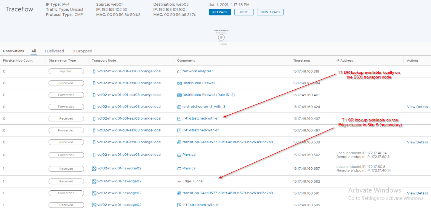
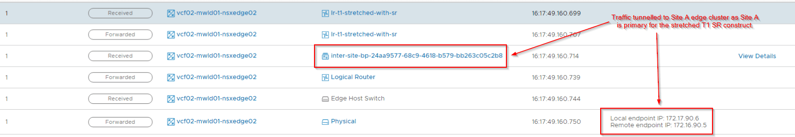
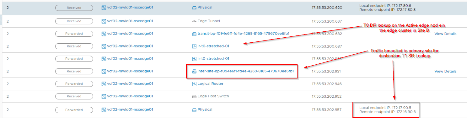
Let’s do a traceflow on the secondary location to confirm this. As mentioned earlier, we get traceflow results only on a site basis.
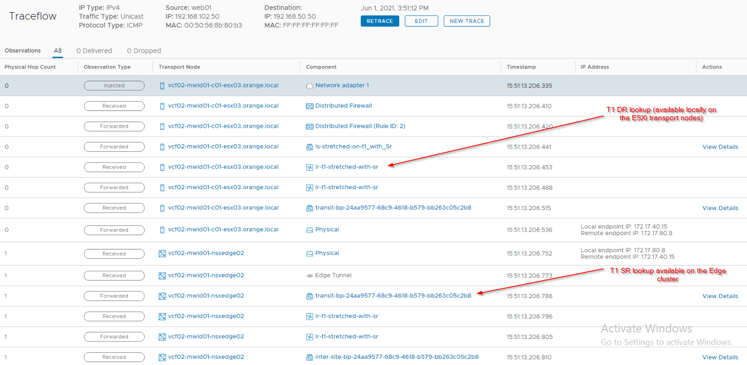
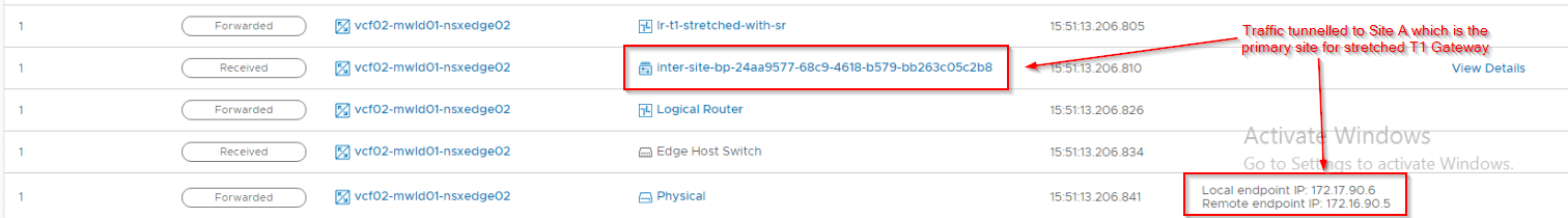
Notice that after the T1 SR lookup on the local edge cluster, traffic is RTEP tunnelled to the T1 SR primary location (Site A) after which we loose traceflow visibility.
The below T1 SR forwarding table on the secondary site shows the next hop pointing to the active edge node on the primary site (Site A)

Northbound from a segment attached to non-stretched Tier 1 Gateway with services (with SR)
Non-stretched Tier 1’s are created from the GM but spans to only one location. Any segments attached downstream to an unstretched T1 Gateway is also unstretched.
For the Primary site:
- T1 DR lookup happens locally on the ESXi transport node.
- For T1 SR lookup, traffic is tunnelled to the active edge node of the primary location’s edge cluster.
- T0 DR lookup happens locally on the active edge node.
- T0 SR lookup also happens locally on the active edge node and the traffic egresses via the T0 uplinks.
For the Secondary site:
- T1 DR lookup happens locally on the ESXi transport nodes.
- For T1 SR lookup, traffic is tunnelled to the active edge node of the secondary location’s edge cluster.
- T0 DR lookup happens locally on the active edge node of the secondary location.
- To reach the T0 SR construct, traffic is RTEP tunnelled to the active edge node of the primary location for egress.
The below sketch depicts the northbound flow for a secondary location.

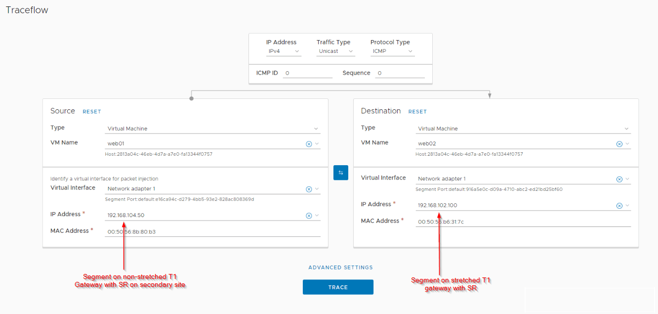
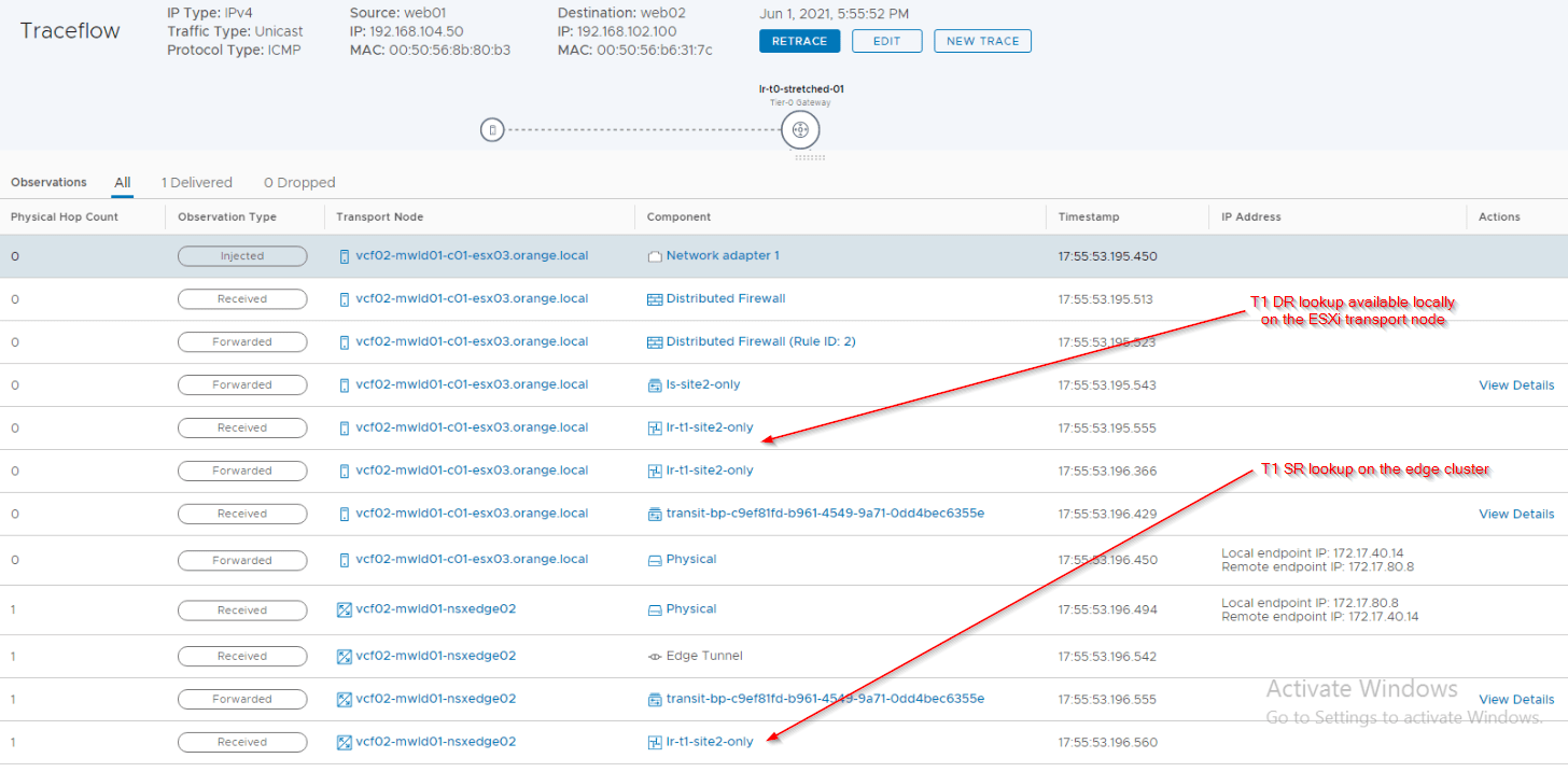
Let’s do a traceflow from the secondary location to confirm this.
As seen in the results, traffic has tunnelled to the primary site for egress.
As mentioned earlier, the southbound flows will have a different traffic pattern than northbound, as routing lookups happen closer to the source.
Let’s take a look at some East-West flows.
East-West between a stretched T1 Gateway with and without services
The below sketch shows an East-West communication between two VMs on the same ESXi transport node in the secondary location (Site B) – one attached to a stretched T1 Gateway with SR and the other attached to a stretched T1 Gateway with DR-only. Site A is primary for both T0 and T1 SRs.

Note the traffic pattern, even though both VMs are on the same ESXi host, traffic had to tunnel to the primary location (Site A) for routing lookups. This is because of the primary / secondary placement of the T1 SR construct.
Let’s do traceflow on the secondary location to confirm this:
As seen in traceflow results, traffic has tunnelled to the primary location after the T1 SR lookup on the local site.
Communication between VMs attached to stretched T1 DR-only gateways or non-stretched T1 gateways with SR will always stay within the location as the routing lookup is available locally.
East-West between a non-stretched T1 Gateway with services and a stretched T1 Gateway with services
The below sketch shows an East-West communication between two VMs on the same ESXi transport node in the secondary location (Site B) – one attached to a non-stretched T1 Gateway with SR and the other attached to a stretched T1 Gateway with SR. Site A is primary for both T0 and T1 SRs.

Note that in this case also, traffic needed to cross locations for communication between VMs on the same ESXi transport node on the same secondary location. This is because the traffic path encountered a stretched T1 SR with primary location as Site A.
Let’s do a traceflow on the secondary location to confirm this:
As you can see traffic getting tunnelled to primary location after the T0 DR lookup on the secondary location.
Below is the forwarding table from the T0 DR construct on the secondary location which next-hops to primary location to reach subnets attached to stretched T1 gateway with SR.

Time to wrap up!!! This has been a lengthier post but I hope this gave you a good understanding on the routing lookups that help you to take good placement decisions.
Thanks for reading.
Continue reading? Here are the other parts of this series:
Part 1 : https://vxplanet.com/2021/04/13/nsx-t-federation-part-1-onboarding/
Part 8 : https://vxplanet.com/2021/06/02/nsx-t-federation-part-8-tier-1-gateway-placement-considerations/
Part 9 : https://vxplanet.com/2021/06/09/nsx-t-federation-part-9-federation-control-plane-explained/
Part 11 : https://vxplanet.com/2021/06/20/nsx-t-federation-part-11-site-failures-and-network-recovery/
