

Welcome back!!! We are at Part 6 of the blog series on NSX-T federation. In this article we will take a look at the configuration and routing of a stretched Active-Active Tier 0 Gateway with location All-Primary. Unlike the previous Tier 0 topologies, we don’t have a secondary location here. All sites are primary and have local egress capabilities. We will discuss that shortly.
If you were not following along, here are the previous parts of this series:
Part 1 : https://vxplanet.com/2021/04/13/nsx-t-federation-part-1-onboarding/
Let’s get started:
Our topology
The topology is exactly same as the one we used in Part 4 except that the stretched T0 locations are ‘All Primary’. This stretched T0 gateway spans across three locations – Site A, B and C. We have six T1 Gateways attached downstream:
- Stretched Tier 1 Gateway with DR only
- Stretched Tier 1 Gateway with SR (primary – Site A)
- Stretched Tier 1 Gateway with SR (primary – Site B)
- Unstretched Tier 1 Gateway in site A (globally provisioned)
- Unstretched Tier 1 Gateway in site B (globally provisioned)
- Unstretched Tier 1 Gateway in site C (globally provisioned)
It has to be noted that a T1 gateway with SR will always be deployed in Primary – Secondary locations. There is no ‘All-primary’ option for a T1 Gateway.
We have logical segments for each Tier 1 gateway. Note that the span of each logical segment depends up on the span of it’s upstream T1 gateway.
- Segment attached to stretched Tier 1 gateway with DR only (192.168.101.0/24)
- Segment attached to stretched Tier 1 gateway with SR – Site A primary (192.168.102.0/24)
- Segment attached to stretched Tier 1 gateway with SR – Site B primary (192.168.106.0/24)
- Segment attached to unstretched Tier 1 gateway in site A (192.168.103.0/24)
- Segment attached to unstretched Tier 1 gateway in site B (192.168.104.0/24)
- Segment attached to unstretched Tier 1 gateway in site C (192.168.105.0/24)

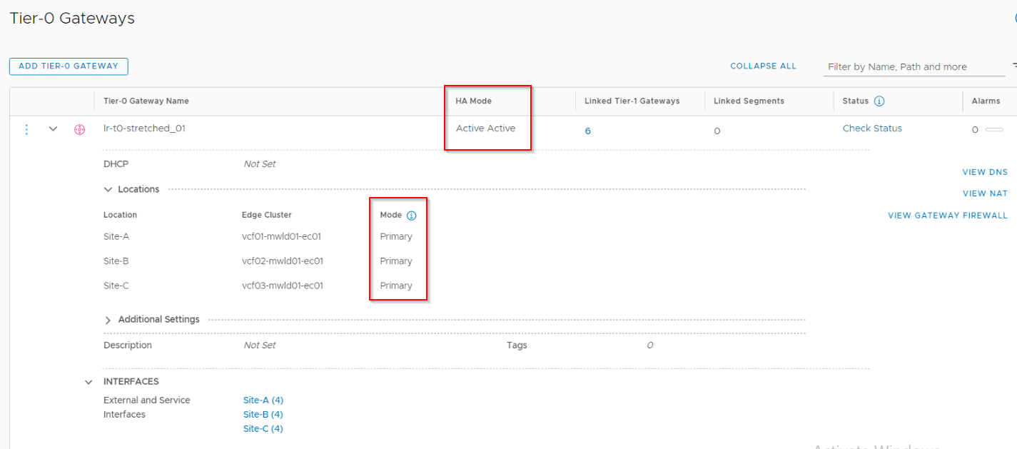
Configuring Stretched A/A Tier 0 Gateway
The stretched T0 gateway is deployed in Active-Active mode with span across all the three locations in ‘All-primary’ topology. Currently only Active-Active T0 gateway supports ‘All-primary’ topology.
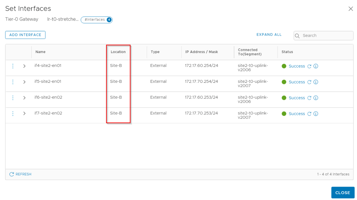
The T0 gateway has 4 uplink interfaces in each location, thereby making a total of 12 across all the three locations. Interfaces (and all global objects) are realized on the local managers based on the span and as such one location doesn’t received the configuration for another location. Below ae the interfaces realized on Site B. The IP/VLAN schema for locations were already discussed in Part 1.
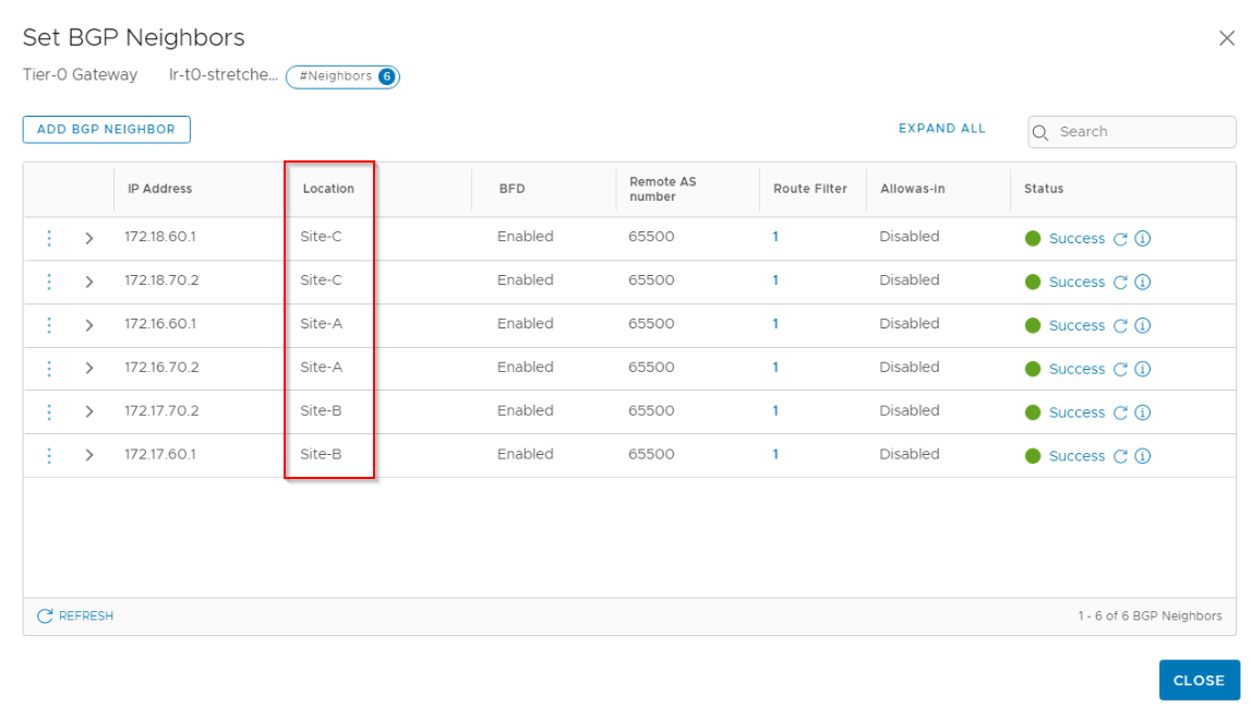
Routing configuration (BGP) is also configured on location basis. Note that this stretched T0 has a single ASN 65200 across locations.
Route-redistribution is also configured on the T0 gateway, note that this also has a span.
Configuring downstream Tier 1 Gateways
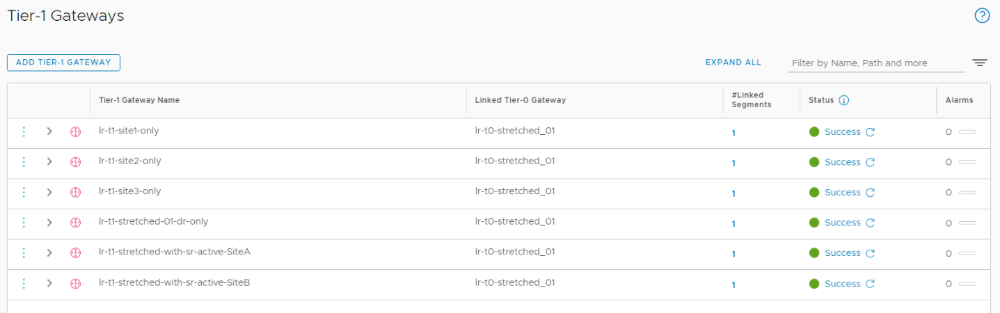
As discussed earlier in the topology details, we have six Tier 1 gateways configured downstream to the stretched T0 gateway.
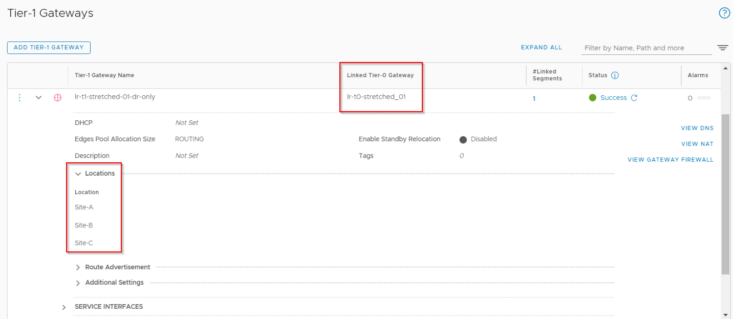
- Stretched Tier 1 Gateway with DR only – (lr-t1-stretched-01-dr-only) – Span across all three locations
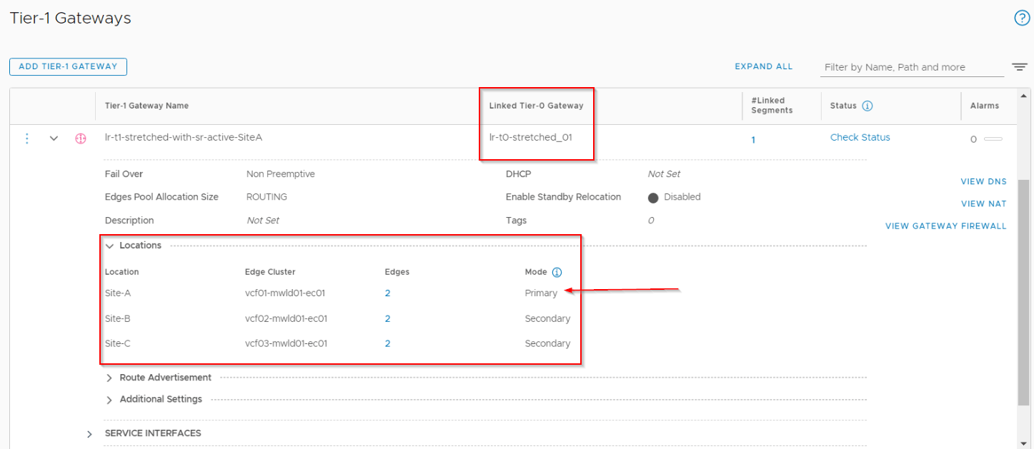
- Stretched Tier 1 Gateway with SR – (lr-t1-stretched-with-sr-active-SiteA) – Span across all locations with Site A as primary
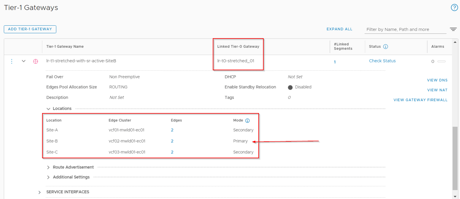
- Stretched Tier 1 Gateway with SR – (lr-t1-stretched-with-sr-active-SiteB) – Span across all locations with Site B as primary
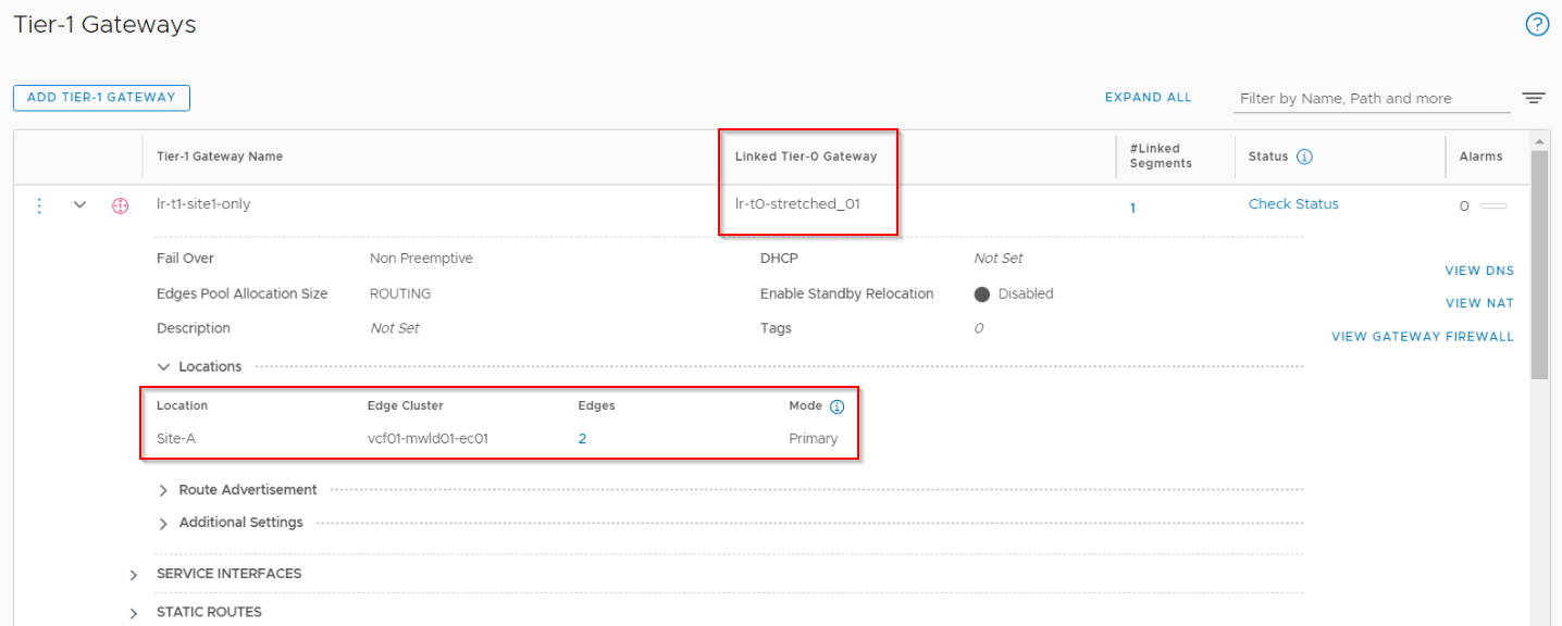
- Unstretched Tier 1 Gateway in site A only – (lr-t1-site1-only) – Span only to Site A
- Unstretched Tier 1 Gateway in site B only – (lr-t1-site2-only) – Span only to Site B
- Unstretched Tier 1 Gateway in site C only – (lr-t1-site3-only) – Span only to Site C
Below is the stretched T1 gateway – DR only. It’s span is equal to the span of the stretched T0 gateway.
Below is the stretched T1 gateway with SR on Site A as primary. It spans across all the three locations.
Below is the stretched T1 gateway with SR on Site B as primary. It also spans across all the three locations.
Below is the unstretched T1 gateway on Site A. It has a local span only on Site A.
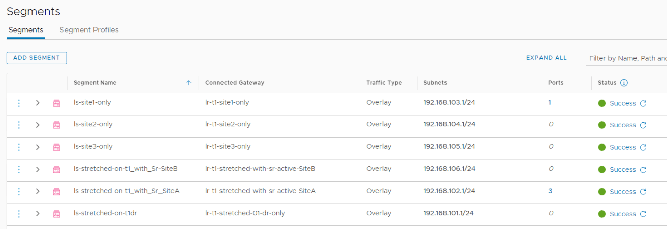
Configuring stretched segments
The span of a segment depends upon the span of the T1 gateway to which it is attached to.
- Segment attached to stretched Tier 1 gateway with DR only (192.168.101.0/24) – ‘ls-stretched-on-t1dr’
- Segment attached to stretched Tier 1 gateway with SR on site A primary (192.168.102.0/24) – ‘ls-stretched-on-t1_with_sr_SiteA’
- Segment attached to stretched Tier 1 gateway with SR on Site B primary(192.168.106.0/24) – ‘ls-stretched-on-t1_with_sr_SiteB’
- Segment attached to Tier 1 gateway in site A only (192.168.103.0/24) – ‘ls-site1-only’
- Segment attached to Tier 1 gateway in site B only (192.168.104.0/24) – ‘ls-site2-only’
- Segment attached to Tier 1 gateway in site C only (192.168.105.0/24) – ‘ls-site3-only’
North – South routing
- In stretched Active-Active T0 gateway with All-primary locations, each location will advertise and receive prefixes from the Leaf switches over the BGP relationship.
- Each location advertises only it’s LOCAL prefixes. Remote prefixes are not advertised.
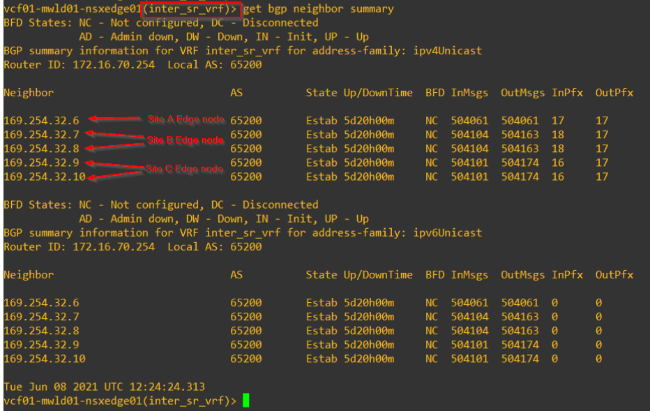
- Inter-SR full mesh iBGP is established between the edge nodes – both with the edges intra-site as well as with edges inter-site.
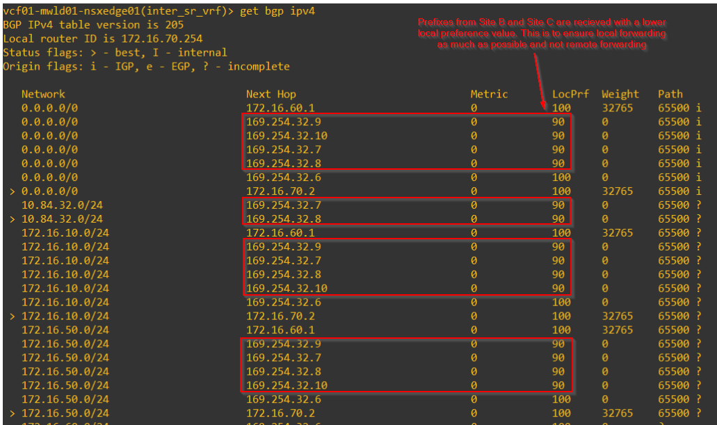
- Prefixes received from the other inter-site edges are received with a lower local preference value (of 90). This is to prefer local forwarding as much as possible than remote forwarding.
- For each location, the prefixes learned on the default vrf (from the leaf switches) will be preferred over the prefixes learned via the inter-sr vrf (other locations)
- As such, each location has local egress to the customer networks.
- To reach customer networks local to a specific location (location specific prefixes), edges from other locations will next-hop to the edges in the specific location for egress.
- Local egress capability is influenced by the placement of the primary location of a stretched T1 gateway with services.
Let’s take a closer look at the above routing behaviour:
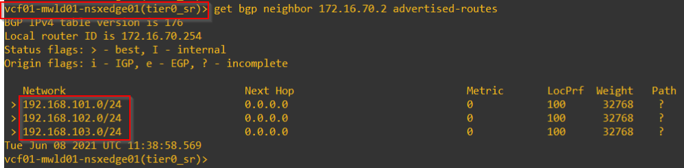
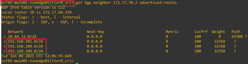
As discussed, each location will advertise only their local prefixes. This includes local T0 subnets, local stretched T1 (DR only) subnets, stretched T1 (with SR) subnets with primary on that location and unstretched T1 gateway subnets on that location.
Below are the routes learned by one of the Leaf switches. Note that I am using single Leaf switch pair for the federation topology, so you might see all the peerings and routes together.
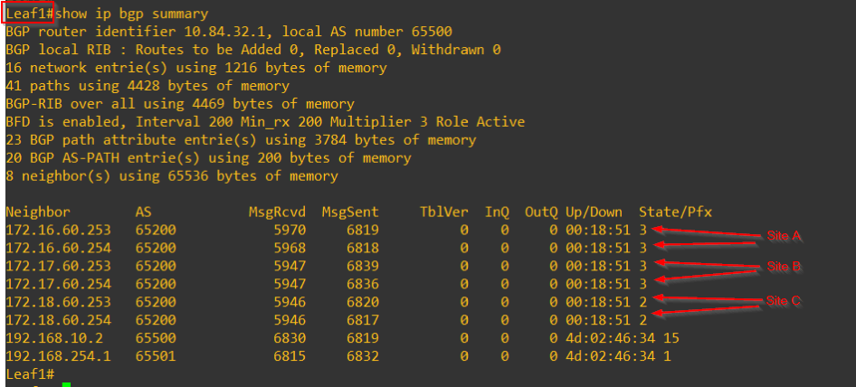
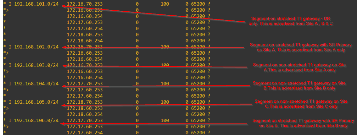
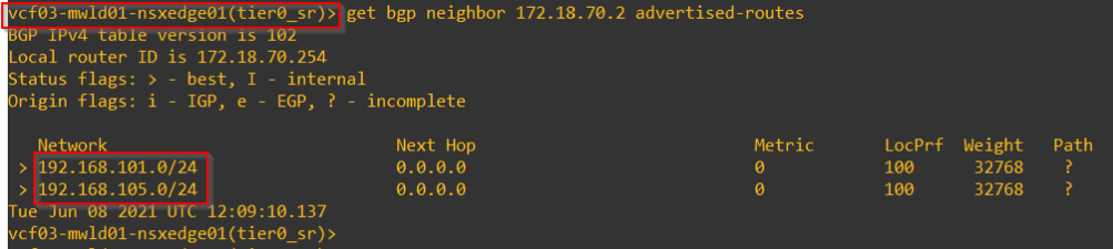
Below are the prefixes advertised from each location.
Below is the inter-SR peering established between intra-site edges and inter-site edges on Site A. We have the same peering on all other locations as well.
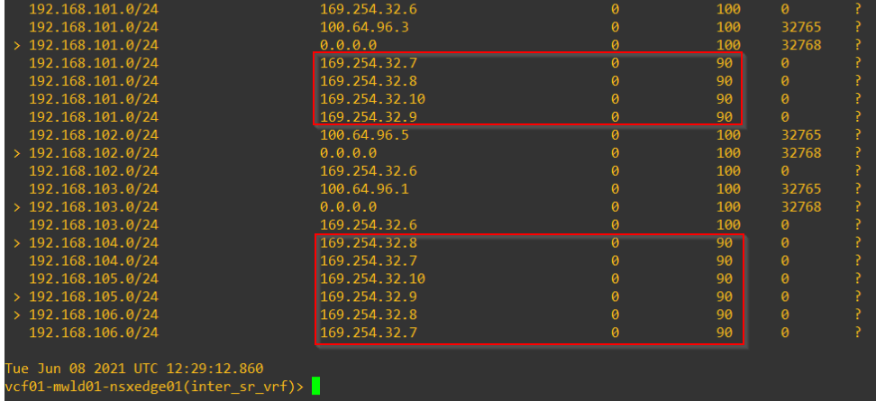
This is the inter-SR BGP table on Site A. Notice that prefixes from Site B and C are received with a lower local preference of 90.
Edge control plane will prefer the prefixes in the default vrf (with higher local preference) and places them in the forwarding table. These prefixes has next-hop pointing to the respective Leaf switches in the location and hence the location will have local egress.
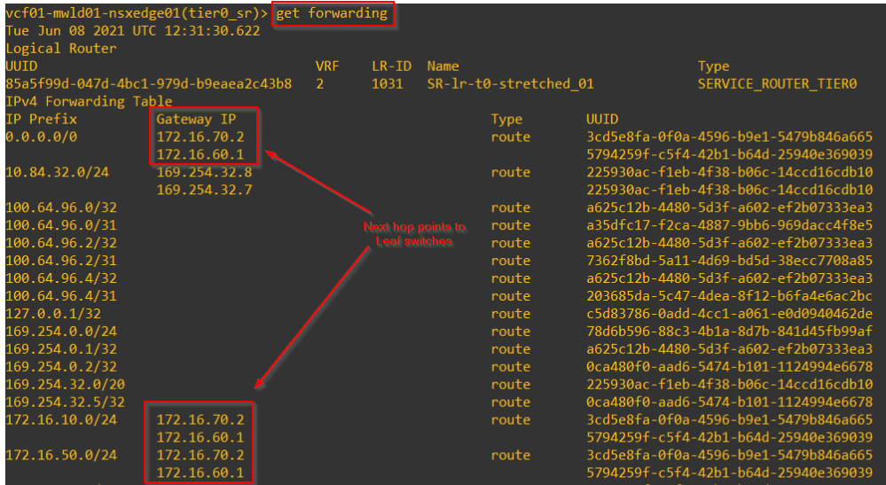
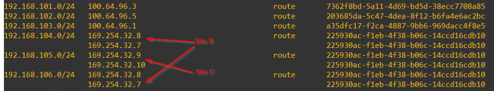
Traffic to location specific overlay segments are routed over to the respective locations.
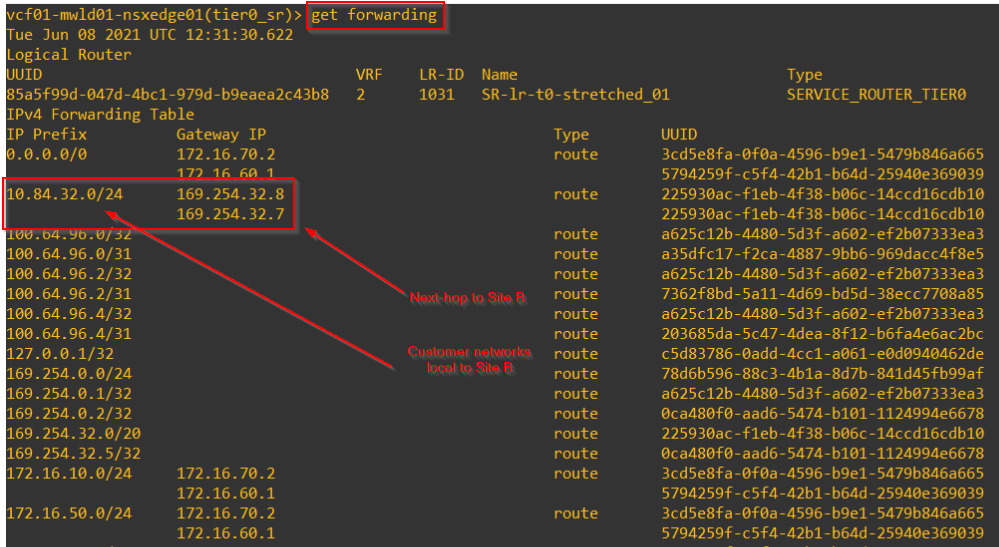
This is the inter-SR bgp table from Site B which also receives prefixes from other locations with a lower local preference and has local egress.
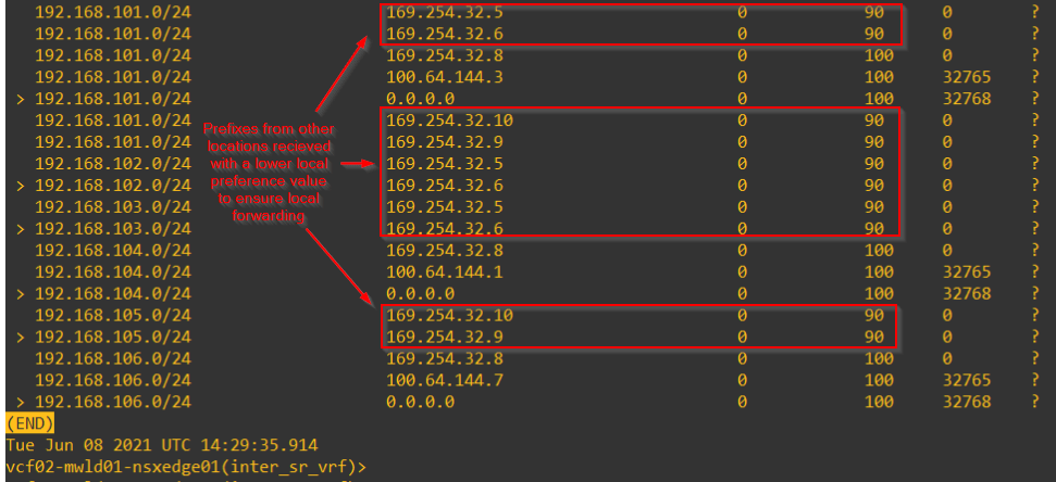
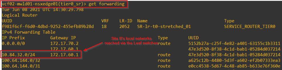
The forwarding table shows the local egress capability.
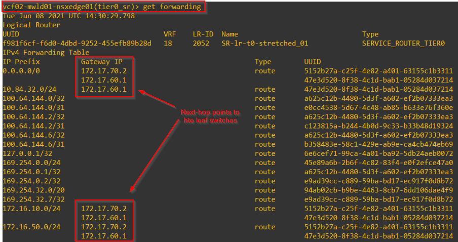
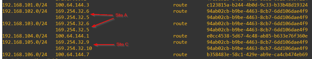
Northbound to location specific customer networks
To reach a location’s local customer networks, the next-hops on other locations are adjusted accordingly in their forwarding tables using the next-hops learned via inter-SR iBGP.
For eg: Site B has a local customer network 10.84.32.0/24 which is reachable over it’s Leaf switches. Site A and C will adjust their next-hops to Site B for reachability.
Local egress and placement of T1 Primary
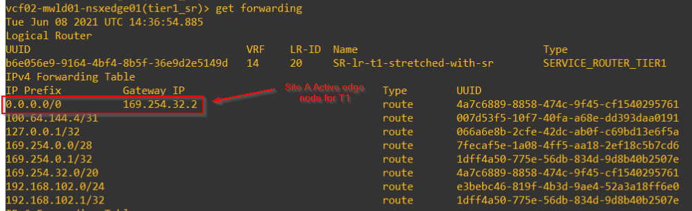
The placement of stretched T1 gateway’s primary location will influence the egress locations as well. For eg: If we have a stretched T1 with SR on Site A as the primary location, all segments downstream to this T1 irrespective of the location, will have Site A as the egress location. Below is the next-hop from Site B Stretched T1 SR that next-hops to Site A
In the next article, we will look at the packet walk for different scenarios of T1 attached to the stretched T0 gateway as well as the N-S and E-W patterns.
I hope this article was informative.
Thanks for reading.
Continue reading? Here are the other parts of this series:
Part 1 : https://vxplanet.com/2021/04/13/nsx-t-federation-part-1-onboarding/
Part 8 : https://vxplanet.com/2021/06/02/nsx-t-federation-part-8-tier-1-gateway-placement-considerations/
Part 9 : https://vxplanet.com/2021/06/09/nsx-t-federation-part-9-federation-control-plane-explained/
Part 11 : https://vxplanet.com/2021/06/20/nsx-t-federation-part-11-site-failures-and-network-recovery/
