

Let’s continue with our blog series on NSX-T Federation, this is Part 5 and we are going to take a closer look at northbound and east-west traffic patterns for segments on different Tier 1 Gateways (stretched/unstretched with and without SR) attached to stretched Active-Active Tier 0 Gateway with location Primary and Secondary which we discussed in Part 4.
If you were not following along, here are the previous parts of this series:
Part 1 : https://vxplanet.com/2021/04/13/nsx-t-federation-part-1-onboarding/
In part 4, we discussed that:
- Both primary and secondary locations advertise and receive prefixes from the respective Leaf switches over their BGP relationship.
- Primary location advertises both local and remote prefixes. Secondary location advertises only it’s local prefixes.
- Primary location gives preference to the prefixes in the default VRF and places them in the forwarding table.
- Secondary location gives preference to the prefixes on the inter-SR VRF (learned form the primary location) and places them in the forwarding table. Hence the next hop from secondary locations points to the primary location for egress.
- Prefixes advertised by the secondary locations over the inter-SR iBGP will be received with a lower local preference (of 90). This is to prefer local forwarding on the edges.
- Prefixes advertised by the primary location over the inter-SR iBGP will be received with a higher local preference and weight. This is to prefer primary location as next-hop for T0 SR.
- For the primary location, any prefixes missing in the default vrf but present in the inter-sr vrf will be placed in the forwarding table with the next hop advertised by the inter-sr vrf bgp table. This way the topology supports location specific egress.
- For the secondary locations, any prefixes present in the default vrf but missing in the inter-sr vrf will be placed in the forwarding table with the next hop advertised by the default vrf bgp table. This way the topology supports local egress to location specific prefixes, instead of getting routed through the default vrf.
- Placement of T1 SR primary location influences the north-south and east-west traffic patterns. In most cases, we co-locate the Tier 1 SR primary location with the T0 primary location to avoid sub-optimal routing.
- Both edge nodes are leveraged for N-S routing (except in some scenarios), hence we have increased ECMP options
Now let’s understand this in more detail by going through some packet walks. Let’s get started.
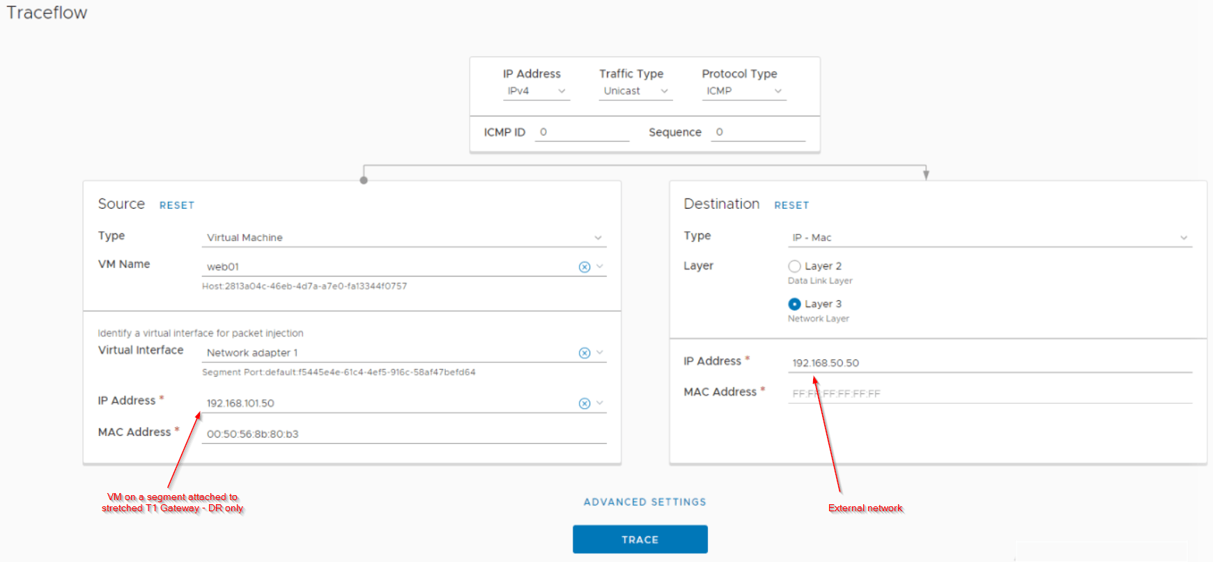
Northbound from a segment attached to stretched Tier 1 Gateway with no services (DR only)
For the Primary location:
- For a northbound flow from a segment attached to the stretched Tier 1 Gateway (DR only), the T1 DR lookup happens locally on the ESXi transport node.
- T0 DR lookup also happens locally on the ESXi transport node.
- For the T0 SR lookup, traffic will be tunnelled (using TEP interfaces) to one of the Active Edge nodes in the primary location (T0 DR to SR ECMP) from where it will egress out over it’s two T0 uplinks.
- Remember that from the ESXi transport nodes to the edges, we have Tier 0 DR to SR ECMP northbound. This ECMP is scalable.
For the Secondary location:
- T1 DR lookup happens locally on the ESXi transport node
- T0 DR lookup also happens locally on the ESXi transport node.
- For the T0 SR lookup, traffic will be tunnelled (using TEP interfaces) to one of the Active Edge nodes in the secondary location (T0 DR to SR ECMP). Secondary location edge nodes will next-hop to both of the Active edge nodes on the primary location (except for location specific prefixes)
- Traffic will be tunnelled again (using RTEP interfaces) from the secondary location edge node to primary location edge node (ECMP).
- Traffic will egress through the two T0 uplinks of the edge node in the primary location.
The below sketch depicts the flow from a secondary location:

Let’s look at the traceflow results from the secondary location to confirm this.
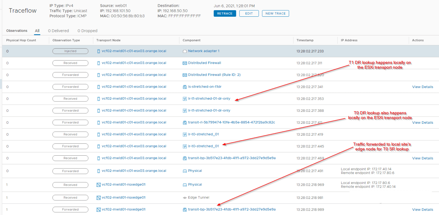
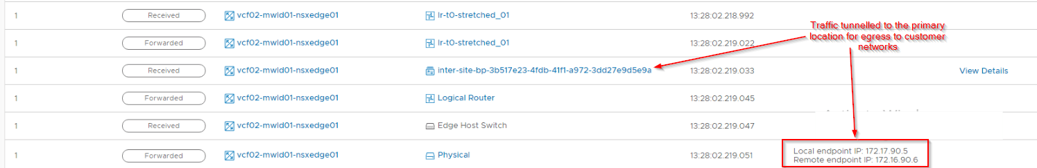
Note that traffic has been forwarded to the primary location (inter-site RTEP tunnel) for egress. As discussed previously, we can’t capture inter-location traceflow results, hopefully it will become available in the future releases.
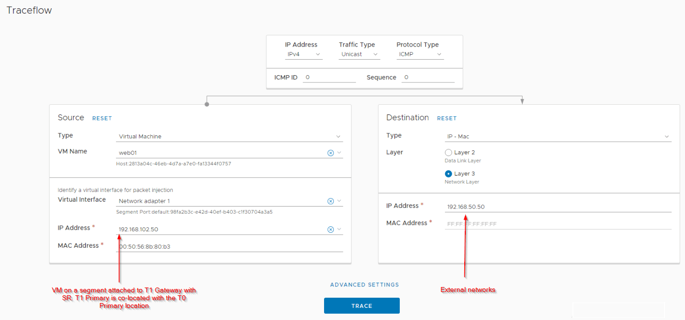
Northbound from a segment attached to stretched Tier 1 Gateway with services (with SR) where T1 primary is co-located with T0 primary
For the Primary location:
- For a northbound flow from a segment attached to the stretched Tier 1 Gateway with SR construct, the T1 DR lookup happens locally on the ESXi transport node.
- To reach T1 SR , traffic is tunnelled (TEP interfaces) to the Active edge node (for T1) of the primary location.
- T0 DR lookup happens locally on the edge node in the primary location.
- T0 SR lookup also happens locally on the edge node and will egress out over it’s two T0 uplink interfaces. Note that only one edge node (the active node of T1) is involved in northbound routing.
For the Secondary location:
- T1 DR lookup happens locally on the ESXi transport node
- To reach T1 SR , traffic is tunnelled (TEP interfaces) to the Active edge node (for T1) of the secondary location.
- Since the T1 SR primary location is co-located with the T0 primary site, traffic will be RTEP tunnelled to primary location’s active edge node for T1 SR.
- T0 DR lookup happens locally on the primary location’s active edge node (for T1 SR).
- T0 SR lookup also happens locally on the same edge node on the primary location and will egress out over it’s two T0 uplink interfaces. Note that only one edge node (the active node of T1) is involved in northbound routing in this case as well.
The below sketch depicts the northbound flow from a secondary site.

Let’s look at the traceflow results on the secondary location to confirm the flow:
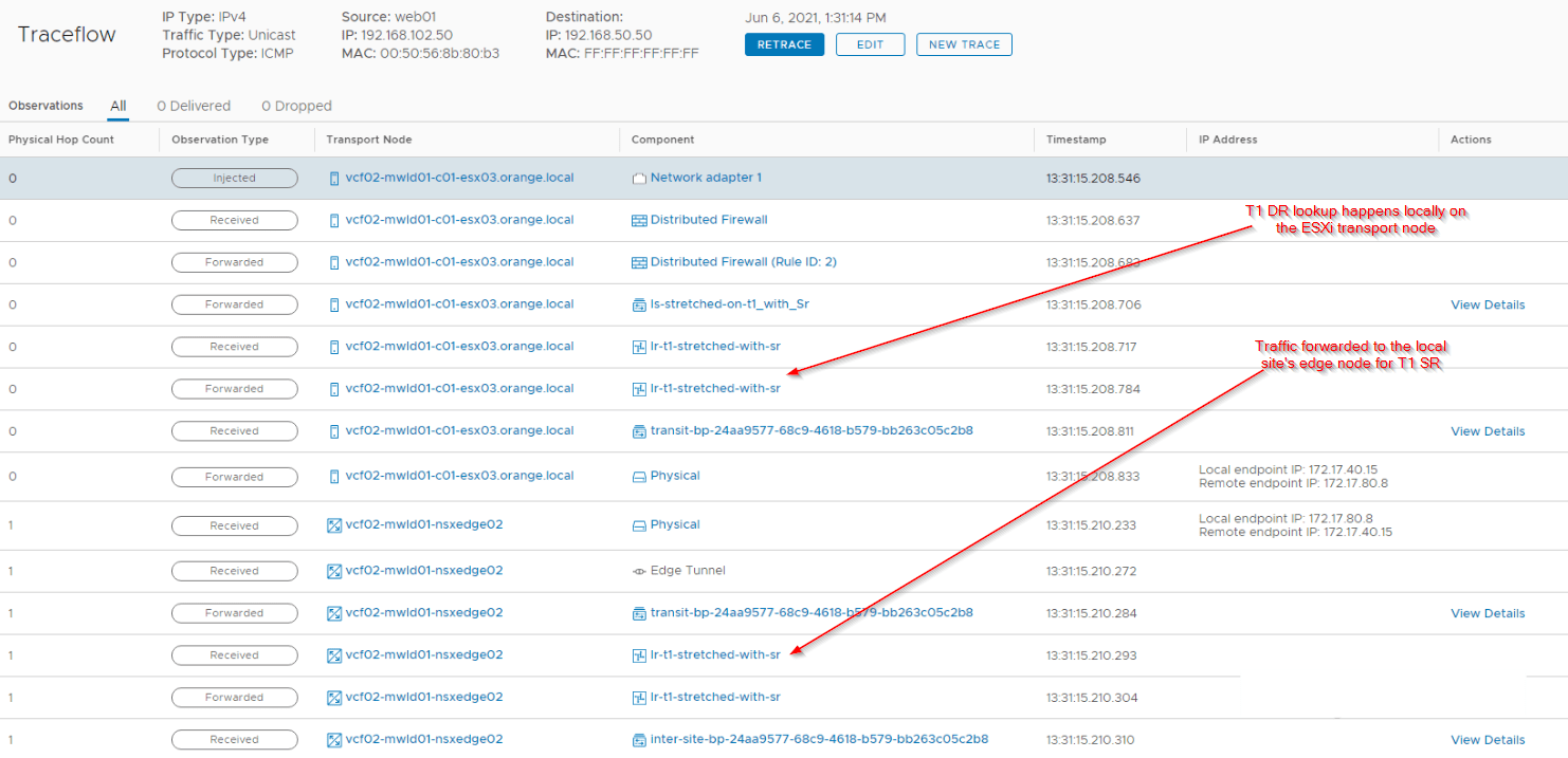
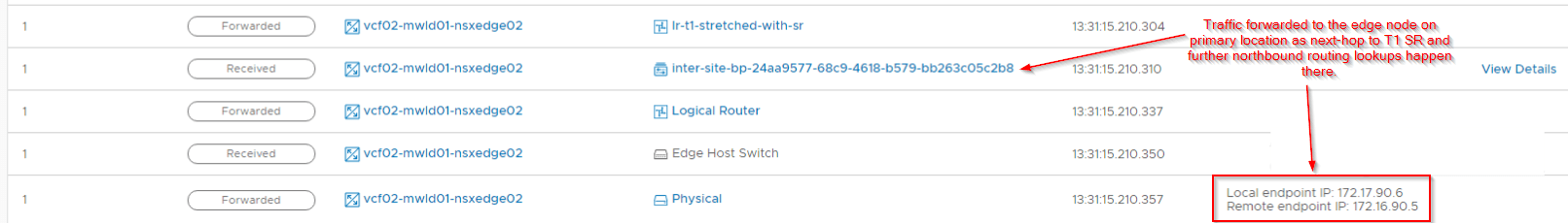
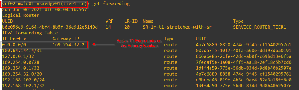
This is the next-hop from the T1 SR of the secondary location which points to the Active T1 SR on the primary location.
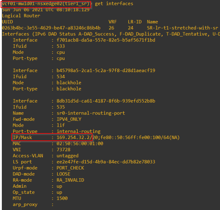
and this is the interface details of the Active T1 SR edge node on the primary location.
Northbound from a segment attached to stretched Tier 1 Gateway with services (with SR) where T1 primary is NOT co-located with T0 primary
This scenario is little different from the previous one, here the primary location of the stretched T1 gateway (with SR) is not co-located with the T0 primary location.
Site A is the stretched T0 primary location and Site B is the stretched T1 primary location.
For the Primary location:
- For a northbound flow from a segment attached to the stretched Tier 1 Gateway with SR construct, the T1 DR lookup happens locally on the ESXi transport node.
- To reach T1 SR , traffic is tunnelled (TEP interfaces) to the Active edge node (for T1) of the primary location.
- Since the T1 SR primary location is on Site B (T0 secondary), traffic will be RTEP tunnelled to Site B’s active edge node for T1 SR.
- T0 DR lookup happens locally on Site B’s active edge node (for T1 SR).
- T0 SR lookup also happens locally on this edge node from where it will be tunnelled (RTEP) back to Site A (primary location) for egress (with ECMP)
For the Secondary location:
- T1 DR lookup happens locally on the ESXi transport node
- To reach T1 SR , traffic is tunnelled (TEP interfaces) to the Active edge node (for T1) of the secondary location.
- T0 DR lookup happens locally on the edge node in the secondary location.
- T0 SR lookup also happens locally on this edge node from where it will be tunnelled (RTEP) back to Site A (primary location) for egress (with ECMP)
The below sketch depicts the northbound flow from a primary site.

Northbound from a segment attached to non-stretched Tier 1 Gateway with services (with SR)
For the Primary site:
- T1 DR lookup happens locally on the ESXi transport node.
- For T1 SR lookup, traffic is tunnelled to the active edge node of the primary location (for T1)
- T0 DR lookup happens locally on the T1 SR active edge node.
- T0 SR lookup also happens locally on this edge node and the traffic egresses via the T0 uplinks. Note that only one edge node (the active node of T1) is involved in northbound routing.
For the Secondary site:
- T1 DR lookup happens locally on the ESXi transport nodes.
- For T1 SR lookup, traffic is tunnelled to the active edge node of the secondary location (for T1).
- T0 DR lookup happens locally on the active edge node of the secondary location.
- T0 SR lookup also happens locally on this edge node from where it will be tunnelled (RTEP) to primary location for egress (with ECMP)
The below sketch depicts the northbound flow from a secondary location.

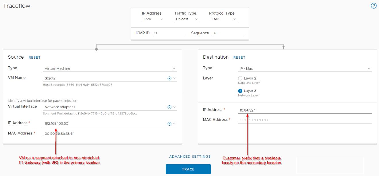
Northbound from primary location to secondary specific customer networks (secondary local egress)
In this scenario (as discussed in Part 4 – Scenario 1), we have few customer networks that are local to Site B (secondary location). The primary location’s T0 SR forwarding table will next hop to the secondary location for egress to these networks.
The below sketch depicts the northbound flow from a segment attached to a non-stretched T1 gateway on the primary location to secondary location specific networks.

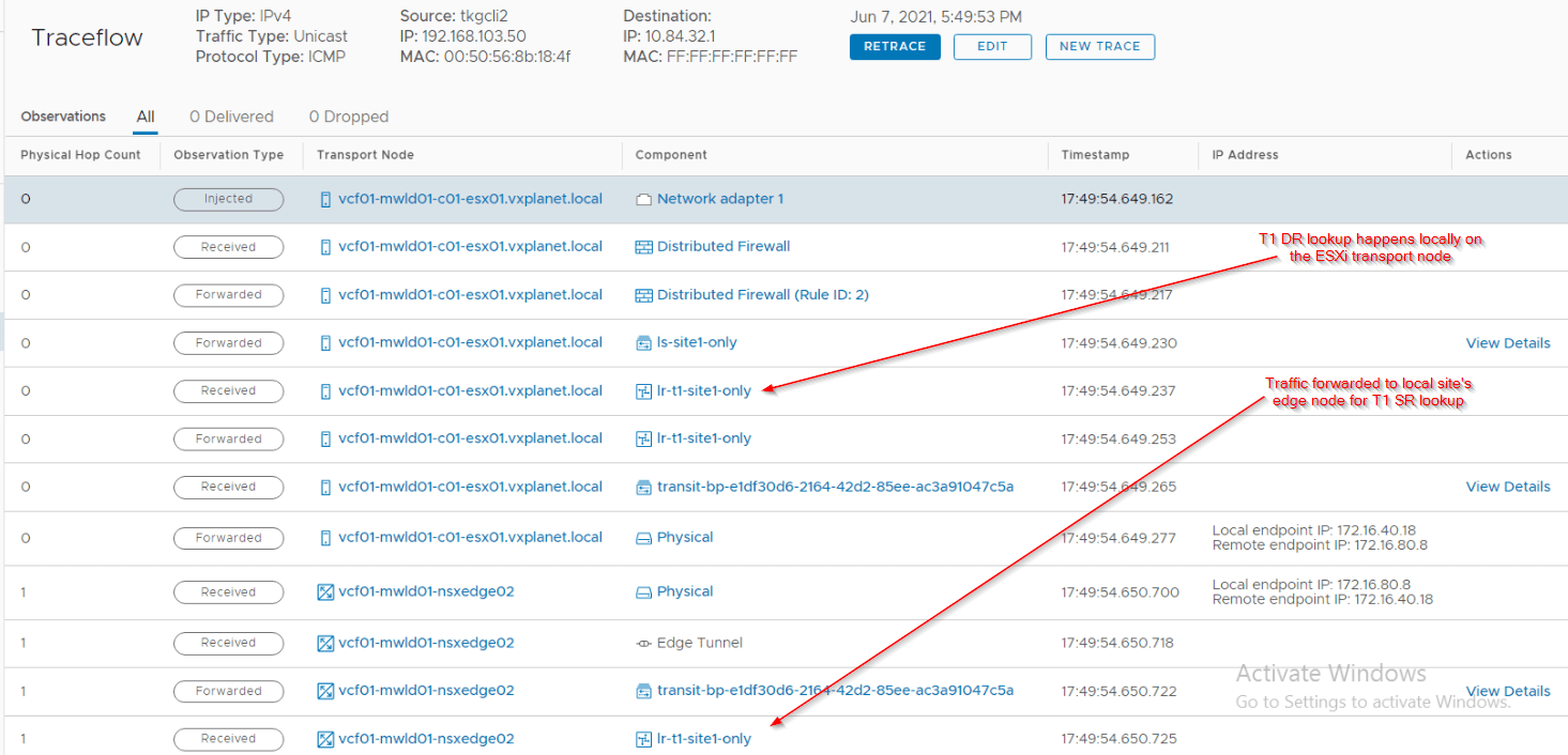
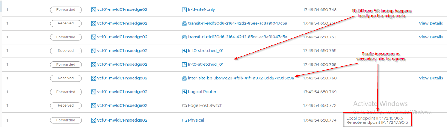
Let’s do a traceflow on the primary location and confirm the flow.
East-West between a stretched T1 Gateway with and without services
The traffic patterns for east-west flows are the same as Active-Standby T0 Gateway which we discussed in Part 2 & 3. This is because T0 SR construct is not involved in East-West routing.
The below sketch shows an East-West communication between two VMs on the same ESXi transport node in the secondary location (Site B) – one attached to a stretched T1 Gateway with SR and the other attached to a stretched T1 Gateway with DR-only. Site A is primary for both T0 and T1 SRs.

Notice that even though both VMs are in the same ESXi transport node in the secondary location, traffic needed to cross to primary location to complete the T1 SR lookup.
East-West between a non-stretched T1 Gateway with services and a stretched T1 Gateway with services
The below sketch shows an East-West communication between two VMs on the same ESXi transport node in the secondary location (Site B) – one attached to a non-stretched T1 Gateway with SR and the other attached to a stretched T1 Gateway with SR. Site A is primary for both T0 and T1 SRs.

As seen, traffic again crossed to primary location to complete the T1 SR lookup.
There are different other scenarios as well for east-west flows, and I hope this article gave you enough guidance to self-understand those scenarios as well.
Let’s wrap up and will meet in the next article – Stretched Active-Active T0 Gateway with location ‘All Primary’. Stay tuned.
I hope this article was informative.
Thanks for reading.
Continue reading? Here are the other parts of this series:
Part 1 : https://vxplanet.com/2021/04/13/nsx-t-federation-part-1-onboarding/
Part 8 : https://vxplanet.com/2021/06/02/nsx-t-federation-part-8-tier-1-gateway-placement-considerations/
Part 9 : https://vxplanet.com/2021/06/09/nsx-t-federation-part-9-federation-control-plane-explained/
Part 11 : https://vxplanet.com/2021/06/20/nsx-t-federation-part-11-site-failures-and-network-recovery/
