
![]()
Welcome back!!! We are at Part 3 of the blog series on NSX-T architecture in vSphere with Tanzu.
In the previous post, we looked at the shared Tier 0 and dedicated Tier 0 deployment options for the Workload clusters at scale. In both deployment options, we used a shared edge cluster for both Tier 1 and Tier 0 gateways. This means that the edge cluster resources were shared for both stateful services (LB, NAT, firewalling etc) and centralized routing. In the shared Tier 0 gateway option, the edge cluster resources are shared by multiple workload clusters which in long-term has the following implications:
- Currently an edge cluster has a limit of 10 edge nodes. Any resource demand from the workload clusters for stateful services beyond this capacity can’t be fulfilled.
- The maximum number of workload namespaces supported per edge cluster is 200.
In this blog post, we will look at a two edge-cluster design and the different topologies available for workload management. In a two edge-cluster design, we have
- An edge cluster dedicated to Tier 0 Gateway
- An edge cluster dedicated to Tier 1 Gateway services.
We have the below three topologies available for workload clusters at scale using the two edge-cluster design.
- Multiple workload clusters on shared Tier 1 Edge cluster upstreamed to shared Tier 0 Gateway
- Multiple workload clusters on dedicated Tier 1 Edge cluster upstreamed to shared Tier 0 Gateway
- Multiple workload clusters on dedicated Tier 1 Edge cluster upstreamed to dedicated Tier 0 Gateway
Let’s get started.
Dedicated Tier 1 Edge clusters and ECMP
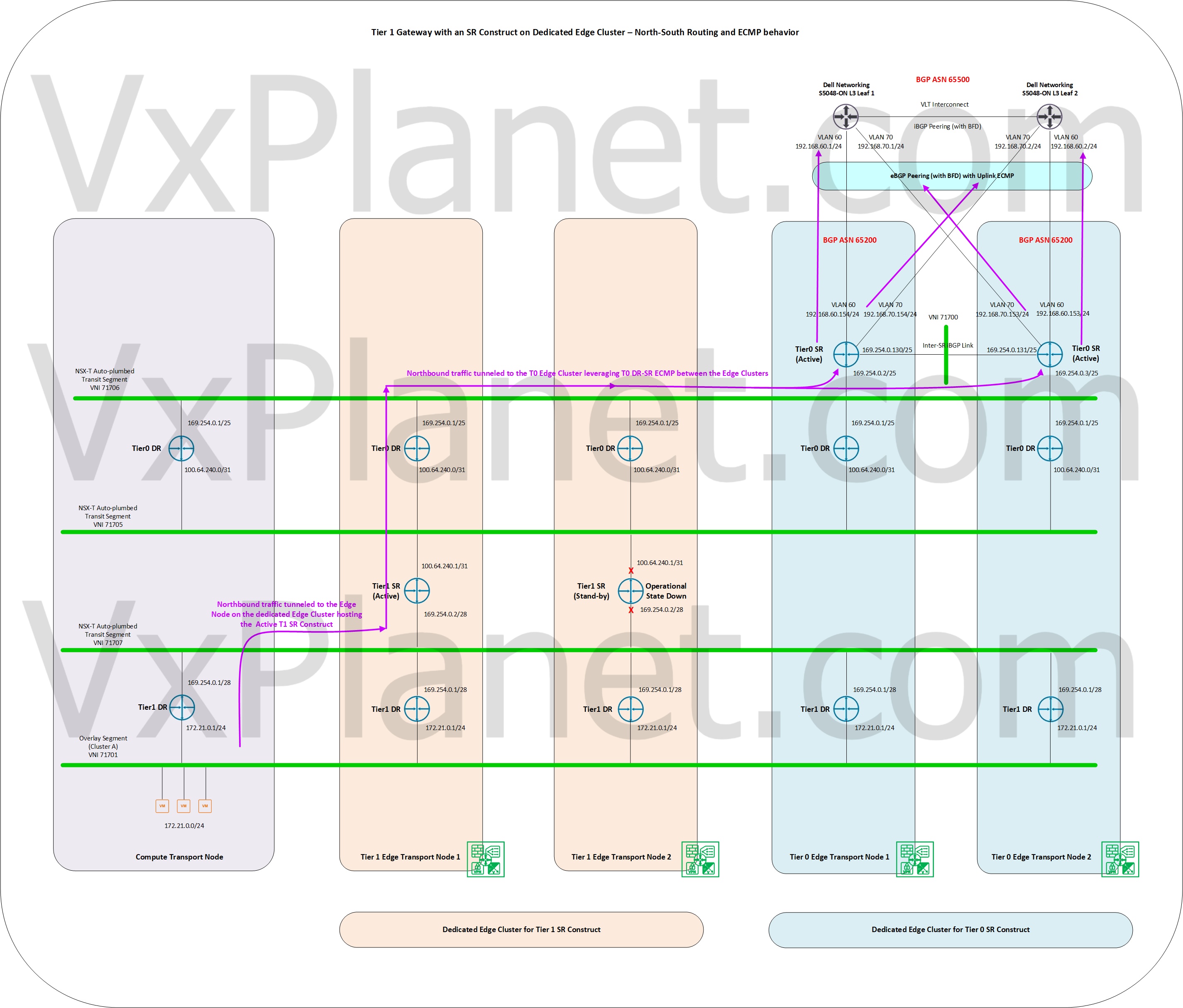
Having a dedicated edge cluster for Tier 1 Gateways provides additional northbound ECMP paths. We achieve scalable ECMP at T0 DR-SR level from T1 edge cluster to the T0 edge cluster as illustrated below.
The below sketch shows the northbound traffic pattern for a workload cluster namespace / TKG cluster leveraging a shared edge cluster for Tier 1 and Tier 0 gateways. Note that in this design, only the active edge node hosting the Tier 1 SR construct is involved in northbound routing. The other Edge node hosting the passive Tier 1 SR construct doesn’t take part in northbound routing, resulting in an overall reduction in the number of ECMP paths northbound from the perspective of a T1 gateway. Edge nodes always strictly follow local upstream forwarding.
This also means that scaling out the T0 edge cluster with additional nodes WILL NOT increase the northbound ECMP paths for a given supervisor namespace as well as a TKG cluster. This is because the supervisor namespace and the TKGs within the namespace scope are attached to a dedicated per-namespace T1 gateway in the new Tanzu architecture. Refer https://vxplanet.com/2021/01/01/nsx-t-architecture-in-vsphere-with-tanzu-part-1-per-tkg-tier1-vs-per-namespace-tier1/

The below sketch shows the northbound traffic pattern for a workload cluster namespace / TKG cluster leveraging separate edge clusters for Tier 1 and Tier 0 gateways. In this design, the Active edge node for the T1 Gateway will do a northbound ECMP to the T0 SR constructs sitting on the separate T0 Edge cluster. This T0 DR-SR ECMP from the T1 edge cluster to the T0 edge cluster is scalable. If we scale out the T0 edge cluster, the T0 DR forwarding table on the dedicated T1 Edge clusters are updated with default routes (ECMP) to the new T0 SR constructs, thereby increasing the number of ECMP paths from the T1 Edge cluster. This way a workload namespace as well as TKGs will achieve scalable ECMP northbound.
Multiple workload clusters on shared Tier 1 edge cluster upstreamed to shared Tier 0 Gateway
In this topology, all the workload clusters will use a shared edge cluster to instantiate the Tier 1 gateway services. The T1 edge cluster provides an aggregated pool of capacity to provision the LBs, NAT, DFWs for all the workload clusters and their respective TKG clusters. The scalability of this topology is limited to 200 namespaces per edge cluster. All the T1 gateways upstream to the T0 Gateway instantiated on a separate edge cluster.

Pros:
- T1 edge cluster resources are consumed only for stateful services and can scale independently from the T0 edge cluster
- This two edge cluster design provides more ECMP paths northbound.
- Edge clusters in this topology reside either on the “Management and Edge vSphere cluster” or on the dedicated “vSphere Edge cluster” and are usually not co-located with the Workload cluster. This makes all resources on the Workload cluster available only for workload management use case.
- Per-workload cluster specific Ingress/Egress CIDR pool helps trackability.
Cons:
- All Workload clusters are on the same Overlay Transport zone. The logical segments for one workload cluster spans across all other workload clusters as well. Hence no logical network separation between the workload clusters.
Multiple Workload clusters on dedicated Tier 1 Edge cluster upstreamed to shared Tier 0 Gateway
In this topology, all the workload clusters will use dedicated Edge clusters to instantiate the Tier 1 gateway services. All resources on the T1 Edge cluster is consumed by only one workload cluster. The scalability of this topology is also limited to 200 namespaces per edge cluster, which would be sufficient for a workload cluster. All the T1 gateways upstreams to the T0 Gateway instantiated on a separate edge cluster as before.
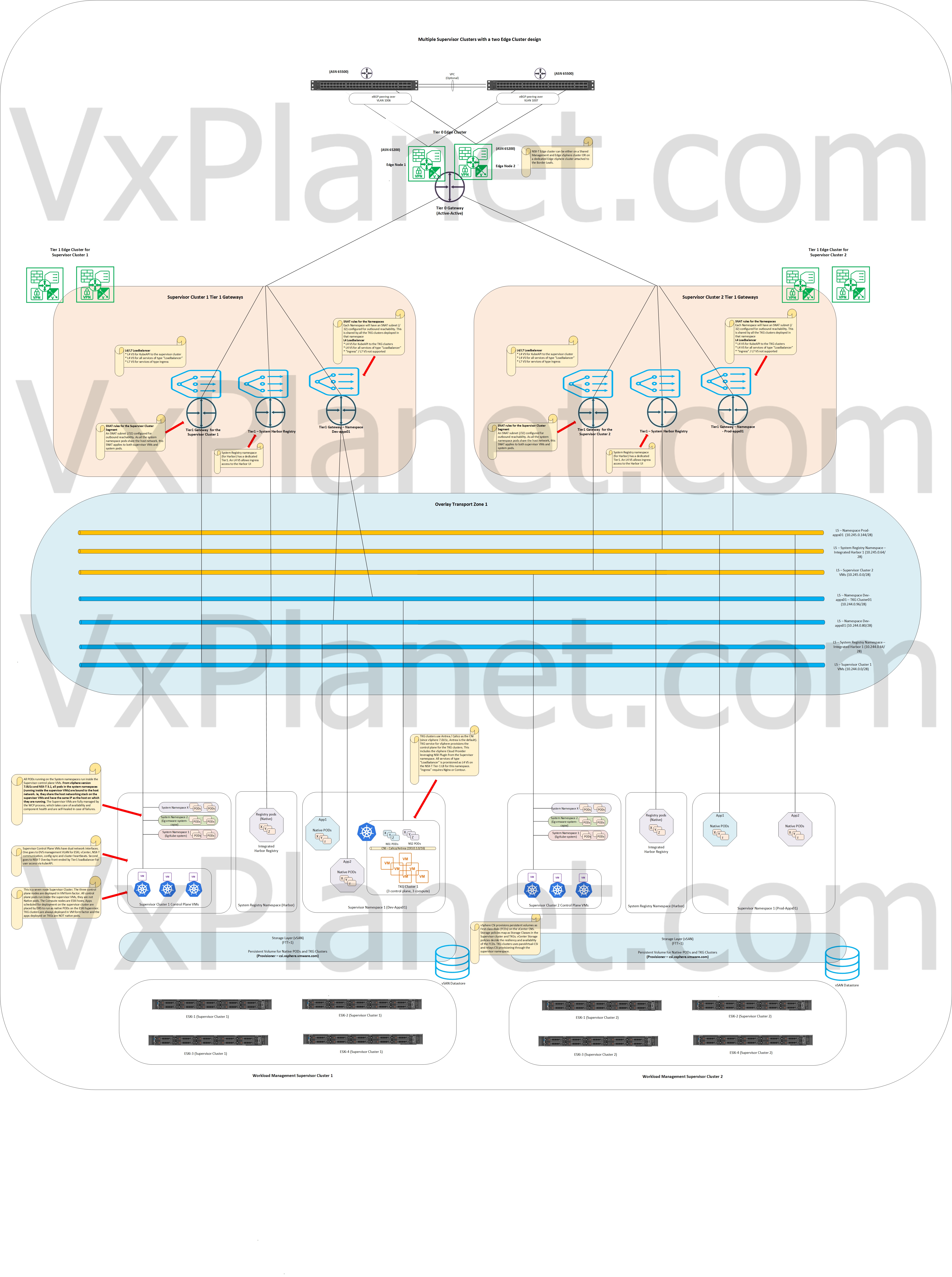
Pros:
- T1 Edge cluster resources are consumed only for stateful services and can scale independently from the T0 edge cluster
- This two edge cluster design provides more ECMP northbound paths
- Per-Supervisor cluster specific Ingress/Egress CIDR pool helps trackability.
Cons:
- All Workload clusters are on the same Overlay Transport zone. The logical segments for one workload cluster spans across all other workload clusters as well. Hence no logical network separation between the workload clusters.
- T0 edge cluster usually resides on the “Management and Edge vSphere cluster” or on the dedicated “vSphere Edge cluster”. T1 edge clusters can co-locate with the workload cluster, hence a portion of the workload cluster resources are consumed to spin up the T1 edge cluster nodes.
Multiple Workload clusters on dedicated Tier 1 Edge cluster upstreamed to dedicated Tier 0 Gateway
Similar to above, in this topology all the supervisor clusters will use dedicated Edge cluster to instantiate the Tier 1 gateway services. These T1 gateways upstream to dedicated T0 Gateway on the separate edge cluster. Each Workload cluster and their associated edge clusters (T1 and T0) are configured on dedicated overlay transport zones, hence there is a logical network level isolation between the workload clusters. In other words, the span of the logical segment of a workload cluster is at it’s cluster boundary only improving multitenancy needs.
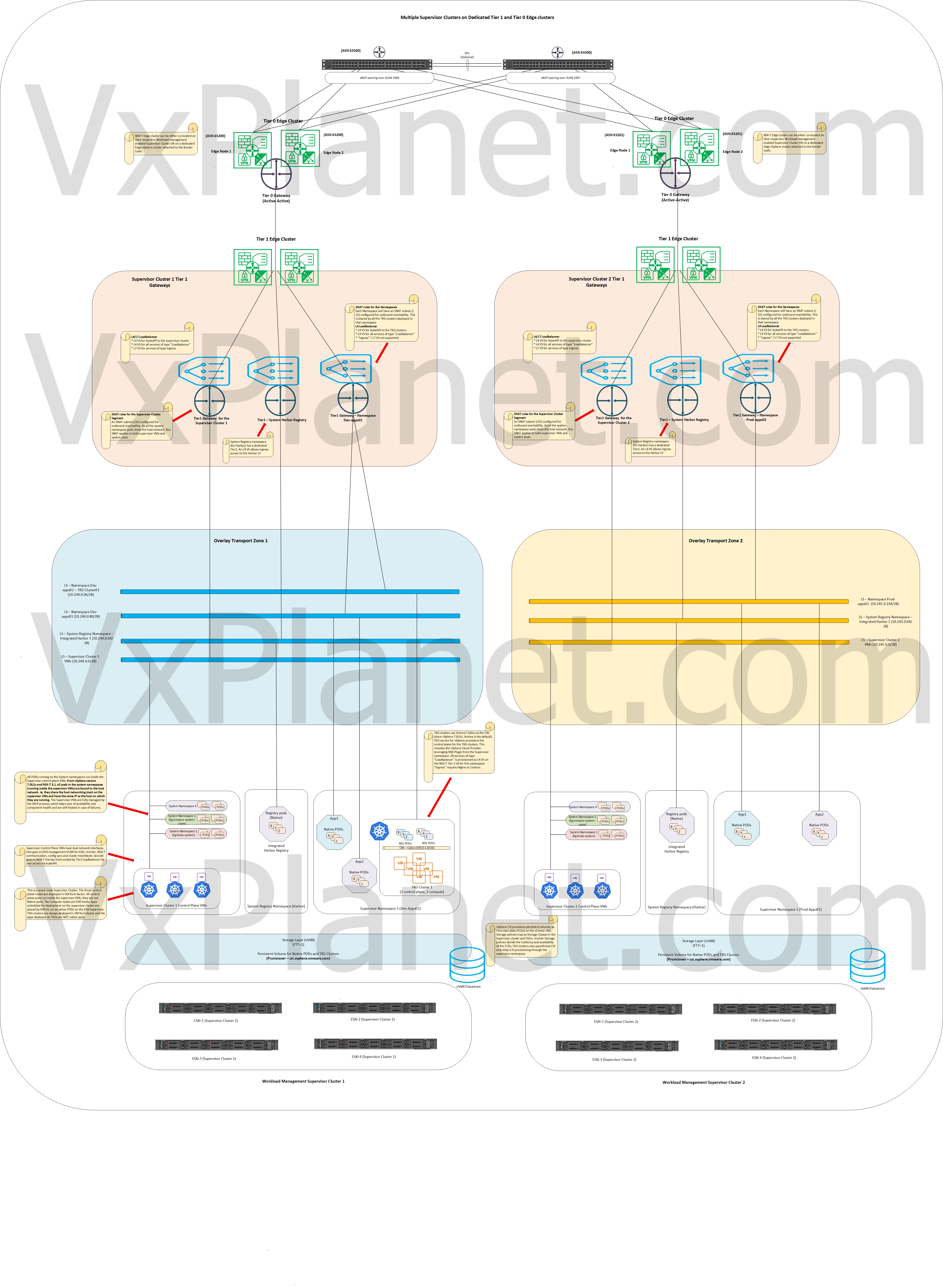
Pros:
- Each workload cluster maps to dedicated overlay transport zones, and as such no overlapping of layer 2 logical segments between workload clusters.
- Each workload cluster is visualized as a separate BGP ASN on the physical networking fabric as there is a 1:1 mapping between workload clusters and T0 gateways. This give more PBR options on the physical fabric.
- Does not require dedicated pod cidr and service cidr for each supervisor cluster.
Cons:
- Usually the T0 edge cluster and the T1 edge cluster are co-located with the workload cluster, hence a portion of the workload cluster resources are needed to spin up the edge cluster nodes.
- Additional BGP peering (and additional ASNs) for each workload cluster that is provisioned.
Configuring workload management to choose the T1 Edge cluster
Choosing the edge cluster for workload management is a one time decision and needs to be taken at the time of initial configuration.
Below we have two edge clusters – one for T1 services and the other for T0

Workload management configuration wizard will list both edge clusters, choose the T1 edge cluster. The uplink connectivity to the T0 gateway is done by the workflow.


Time to wrap up this post and will see you in Part 4 where we will discuss about Proxy-ARP gateways.
I hope the article was informative. Thanks for reading
Continue reading? Here are the other parts of this series:
Part 4 : https://vxplanet.com/2021/02/12/nsx-t-architecture-in-vsphere-with-tanzu-part-4-proxy-arp-gateways/

hi, HariKrishnan,
How to config to support “Per-workload cluster specific Ingress/Egress CIDR”? As I understand, in one Supervisor Cluster, all workload cluster can only share the same Ingress/Egress CIDR pool, correct?
Hi Jinfa, Thanks for reading the article. It looks like there is a slight confusion. I refer to Workload cluster as the one enabled with Workload management which itself is the supervisor cluster. I refer to the TKG guest clusters as Compute clusters – please correct me if I am wrong.
Thanks
Hari