

Introduction
VMware Cloud Foundation 4.0 got released to GA few weeks back with support for vSphere Workload Management (vSphere 7.0 with Kubernetes) and other enhancements. Taken from the release notes, here are few of them.
- Support and workflow to enable K8S Workload Management in vSphere 7.0 (The actual enablement is however done via vCenter Console)
- Consolidated NSX-T architecture – NSX-T for both Management and Compute Workload Domains. (No NSX-V from VCF 4.0)
- Automated Deployment of NSX-T Edge Clusters for both Management and Compute VI Workload Domains.
- Support for vSphere Lifecycle Manager (vLCM) enabled Workload domains
- Support for flexible NSX-T Deployment Options – either have dedicated NSX-T Manager cluster for each WLD or share NSX-T Manager Cluster across WLDs. NSX-T Edge Clusters are however local to each WLD.
- Alignment with VMware Validated Design (VVD) 6.0.
For a full listing of new features, BOM and known issues, please read the complete release notes at the below link:
Note that VCF 4.0 is currently available for Greenfield deployments only. This means that we can’t upgrade from earlier versions of VCF to 4.0. For Brownfield deployments, we probably need to wait for the next release(s). Also the VCF Workflow to deploy Enterprise PKS is not available in VCF 4.0.
This two part blog series covers the NSX-T Edge cluster automated deployment workflow for the Compute VI workload domain and the Edge architecture which is Single-NVDS Multi-TEP on vSphere Compute DVS.
In Part 1, we will cover the Edge Architecture and the VCF 4.0 Workflow to deploy NSX-T Edge Cluster on the VI Workload domain (VI WLD Cluster is a Shared Compute and edge Cluster). Note that NSX-T Edge Cluster for the Management WLD was already deployed as part of SDDC bring-up process. The architecture is the same as described below.
In Part 2, we will do a walkthrough on the NSX-T 3.0 console and review the configuration & deployment of Edges along with some additional considerations that we need to be aware of.
Let’s get started:
NSX-T 3.0 Edge Cluster Architecture (Single NVDS Multi-TEP)
Below is the Edge architecture that is deployed by VCF 4.0 both on the Management WLD and Compute VI WLD. The deployment model is Single NVDS Multi-TEP with deterministic peering using Named Teaming Policies.
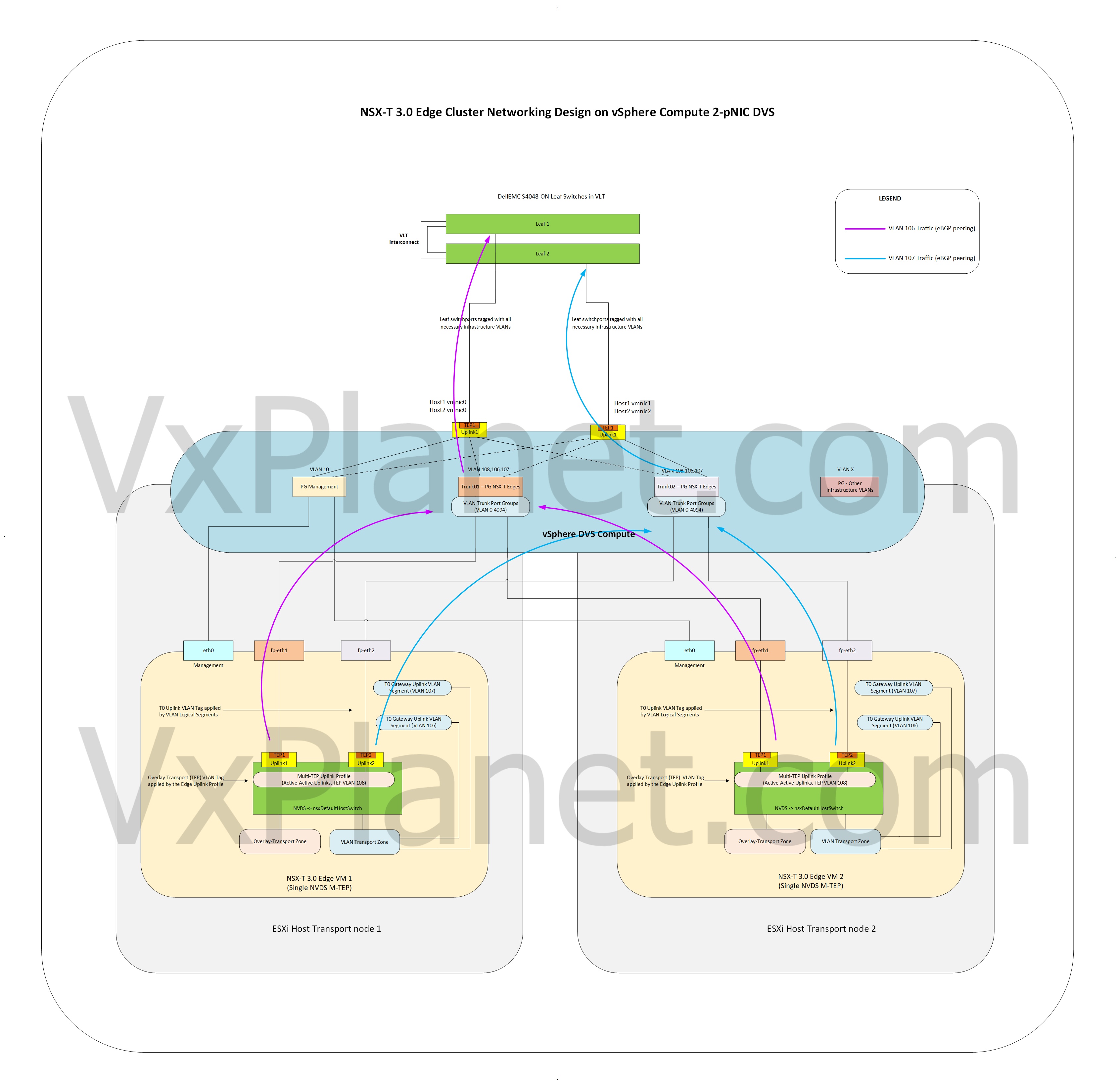
A quick summary on the architecture, we will cover more details in Part 2.
- As mentioned earlier, the architecture is Single-NVDS Multi-TEP
- Edges are deployed on Compute ESXi hosts on the VI Workload domain which use 2XpNIC host networking.
- Host TEP and Edge TEP are on separate VLANs which are routable. This is a requirement whenever Edges are deployed on host vSphere DVS or host NVDS which has a TEP interface.
- The ESXi hosts in the Compute VI WLD are L2 Uniform. This is needed to support Edge vMotions.
- Named Teaming Policies are used to achieve deterministic eBGP peering over specific uplinks to the Leaf switches. Deterministic steering for infrastructure VLANs (vSAN, vMotion etc) are already taken care on the DVS Portgroups during the bring-up of Workload domains
- A Tier 0 Gateway is instantiated on this Edge cluster and does eBGP peering with the Leaf switches (over two VLANs) based on the configuration input.
- If the usecase for Compute VI WLD is for vSphere Workload management, then only one Edge cluster is supported for one Overlay Transport zone.
As an FYI, also note that:
- The NSX-T manager clusters of Compute WLDs reside on the management WLD.
- Additional VI WLDs can either share the NSX-T Manager cluster or have dedicated NSX-T manager clusters depending on the level of isolation needed.
- VCSA instance of the VI WLD also resides on the Management WLD.
IP Configuration Schema
This is the IP Schema for the VI Workload domain used for this article. The Management WLD has already been configured as part of SDDC Bring-up and is not covered in this article.

This is the Edge Node specific details which is given as input to the workflow.

Configuration Workflow
With all the inputs ready, let’s move on to the configuration workflow.
Let’s login to SDDC Manager and navigate to the context of the VI Workload domain where we want the Edge cluster to be deployed. In our case the VI WLD is “WLD2-K8S-TKG” as the intention of this WLD is to enable Workload Management to deploy TKG Clusters with NSX-T Stack.

This WLD has a single Compute cluster with 3 hosts.

We will add an NSX-T Edge Cluster to this vSphere Cluster.

Verify that we meet all these pre-requisites. We need to satisfy two of them – BGP configuration on the Leaf switches and DNS, let’s do that before we proceed.

Configure the necessary eBGP peering on the Leaf switches beforehand, so that once the T0 Edges are deployed by the VCF Workflow, BGP Peering between Edges and Leafs are established automatically. Note that Leaf 1 and Leaf 2 peers with Edges via VLAN 106 and VLAN 107 respectively.

Add DNS host records for the Edge management network and verify name resolution.

Once completed, we can resume the workflow.
Provide the necessary configuration inputs for Edge Cluster name, ASN, T0/T1 names and passwords.


If our usecase is to enable Workload Management in vSphere, then choose “Workload Management”, else “Custom”. Workload Management use case will deploy T0 Gateway in Active-Active mode with eBGP as the routing type. A Large Form factor is also chosen for the Edge Sizing as it needs to deal with multiple T1s and Loadbalancers.

Next provide the Edge node details as per the IP Schema we created earlier.

Make sure that VLAN 106 peers with Leaf 1 and VLAN 107 peers with Leaf 2. If we make a mistake here, the post-validation fails and we need to restart the workflow.


Once both Edge details are entered, hit Next to validate the provided inputs.


If validation succeeds, it is safe to initiate the deployment.

This will take some time, we have some time now to grab a coffee and when we come back, the deployment should have succeeded.

SUCCESS!!!
What we should see now is that the Edge nodes are successfully deployed as per the architecture we discussed in the beginning, added to the Edge cluster, a T0 Gateway instantiated with successful deterministic eBGP peering with the leafs – and that’s almost everything.
We can now spin up Tier 1s as per the Workload requirements.
In the next part, we will do a walkthrough of the NSX-T 3.0 console and review the configuration & deployment of Edges along with some additional considerations that we need to be aware of.
I hope this article was informative.
Thanks for reading
Continue reading? Here is the Part 2 of this series:
