

Until NSX-T version 3.2, Proxy ARP configuration on the T0 Gateway required that the gateway to be deployed in Active-Standby mode. I wrote an article around the same for use with vSphere with Tanzu during February last year. If you missed it, you can read it below:
https://vxplanet.com/2021/02/12/nsx-t-architecture-in-vsphere-with-tanzu-part-4-proxy-arp-gateways/
To understand what Proxy ARP is, it is a technique where a router responds to ARP requests destined to devices attached to it’s different interfaces. In NSX-T, the Tier 0 gateway responds to ARP requests destined to the loadbalancers and NAT interfaces created on the Tier 1 gateway attached downstream. This way, a subset of the Tier 0 uplink subnet is carved out to provision the subnet for loadbalancers and NAT rules on the Tier 1 gateways, thereby completely eliminating routing between NSX-T edges and the ToR switches.
Proxy ARP based T0 gateway deployment doesn’t require any routing to be enabled between the Tier 0 Gateway and ToR switches and is ideal for Test and PoC environments.
With NSX-T version 3.2 and above (I am using NSX 4.0 for this article), we can now have Proxy ARP enabled on T0 Gateways when deployed in Active-Active mode thereby leveraging both edge nodes for dataplane traffic. However, there is a slight difference in the way Proxy ARP entries are handled by the edge nodes when compared to Active-Standby mode which we will discuss shortly.
Note that Proxy ARP doesn’t have any manual configuration, it is enabled by default whenever a loadbalancer VIP or NAT rule is created using an IP address from the subnet used on the Tier 0 interfaces.
In this article, we will take a closer look at Proxy ARP handling on T0 Gateway when deployed in Active-Standby and Active-Active mode along with edge failover scenarios as well.
Let’s get started.
Difference in Proxy ARP handling by the T0 Gateways when in Active – Standby and Active – Active mode
For a T0 Gateway in Active – Standby mode, the Proxy ARP entries are pushed by the management plane to the external uplink interfaces of both edge nodes. However only one edge node is Active, and this edge node will send gratuitous ARP to the upstream ToR switch and consequently responds to ARP requests from clients. The standby edge node, even though it has the Proxy ARP entries, will not respond to ARP requests and will take over in the event of active edge node failure.
For a T0 Gateway in Active – Active mode, management plane can’t push the same Proxy ARP entries to both edge nodes as both edges are active and will respond to ARP queries from ToR which will eventually create ARP conflicts. Hence management plane chooses one edge node to be authoritative for few Proxy ARP addresses and the other edge node for another set of Proxy ARP addresses and so on. This way if the T0 gateway is scaled to more number of edge nodes, the Proxy ARP addresses will be distributed across all of the edge nodes. One Proxy ARP addresses will not have more than one edge node as authoritative.
Proxy ARP on T0 Gateway (Active- Standby mode)
The below sketch shows a T0 gateway in Active-Standby mode with Proxy ARP enabled.
- Routing is not involved in Proxy ARP based design
- Each edge node has only one uplink interface attached to the ToR switch (one interface VLAN only). Hence the Tier 0 gateway has 2 external interfaces in total, one over each edge node.
- A default static route (0.0.0.0/0) is configured on the T0 gateway which next-hops to ToR switch for northbound reachability.
- A single edge cluster is leveraged for both Tier 0 and Tier 1 gateways
- Few stateful services are running on the T1 gateway on IP addresses that fall into the T0 Gateway external interface subnet.
- We see Proxy ARP addresses mapped to the external interface of both edge nodes, but only the active edge node responds to ARP requests.

Now let’s do the configuration and verify this:
We have the T0 Gateway deployed in Active-Standby mode with two external interfaces – one over edge node 1 and the other over edge node 2.


Let’s create a T1 gateway instantiated on the same edge cluster as the T0 gateway. We will instantiate few stateful services (NAT and LB) using an IP block from the T0 gateway’s external address subnet, and enable route advertisements for the same.

Below are the SNAT rules and Virtual services for egress and ingress respectively for the workloads attached to the T1 gateway.


At this moment, we should see the Proxy ARP addresses pushed to the external interfaces of both edge nodes.


and the services should be reachable. We should now have egress and ingress capability for the workloads under the T1 gateway.

The ARP table on the upstream ToR switches will point to the external interface of the active edge node to access the workloads.

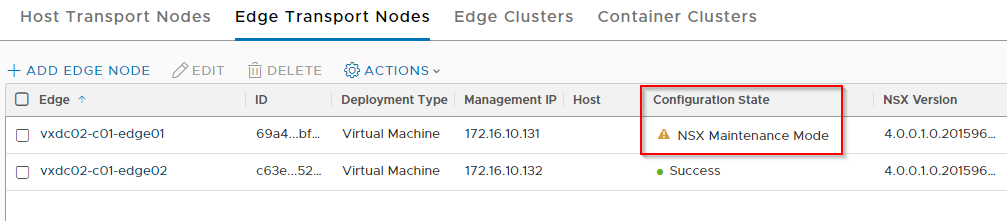
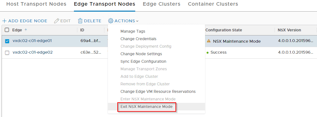
Edge failover
Now lets do an edge failover and verify the ARP table. The standby edge node should take over and issue gratuitous ARP to the ToR switches and we should see that the tables are updated correctly with the new active edge node’s mac address.

Proxy ARP on T0 Gateway (Active- Active mode)
The below sketch shows a T0 gateway in Active-Active mode with Proxy ARP enabled.
- Routing is not involved in Proxy ARP based design
- Each edge node has only one uplink interface attached to the ToR switch (one interface VLAN only). Hence the Tier 0 gateway has 2 external uplink interfaces in total, one over each edge node.
- A default static route (0.0.0.0/0) is configured on the T0 gateway which next-hops to ToR switch for northbound reachability.
- A single edge cluster is leveraged for both Tier 0 and Tier 1 gateways
- Few stateful services are running on the T1 gateway on IP addresses that fall into the T0 Gateway external interface subnet.
- We see Proxy ARP addresses distributed across the active edge nodes and the respective edge nodes respond to ARP requests from the ToR switches

Now let’s do the configuration and verify this:
We have the same T0 Gateway but deployed in Active-Active mode with two external interfaces – one over edge node 1 and the other over edge node 2. The same T1 gateway and stateful services as before are used.


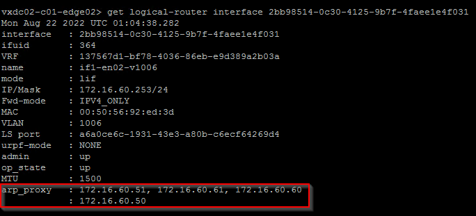
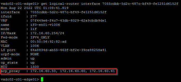
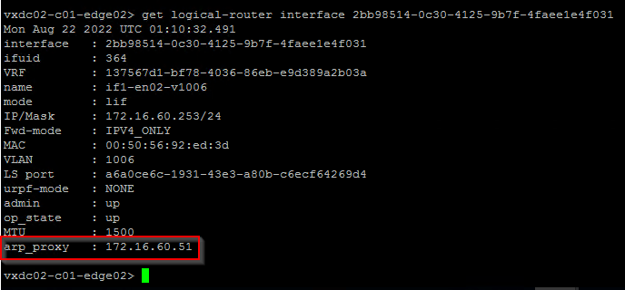
We see that Proxy ARP addresses are distributed across edge node 1 and edge node 2, and each edge node is authoritative for specific Proxy ARP addresses.


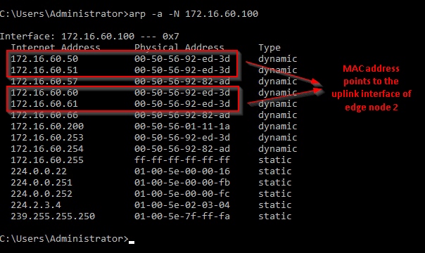
We see ARP table on the ToR switches has entries of both edge node 1 and edge node 2 based on the Proxy ARP addresses they own.

Edge failover
Now let’s see what happen when an edge node fails. The Proxy ARP addresses owned by the failed edge node will be distributed by the management plane to the other available edge nodes of the T0 gateway.
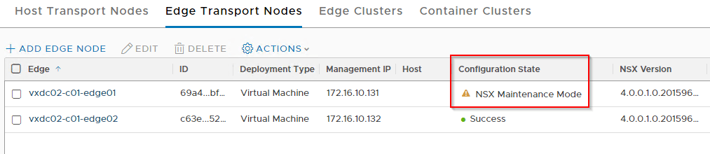
The edge node that took over the Proxy ARP addresses will now issue a gratuitous ARP to the ToR switches thereby updating the ARP table.
Edge failback
When the failed edge node comes back online and have successfully registered with the management plane, it takes ownership of few Proxy ARP addresses from the other edge nodes and sends gratuitous ARP to the upstream ToR switches.
One thing to be noted is that the failover and failback isn’t as quick as BFD, it completely depends on how and when the ARP tables are updated. For example, if there are 200 Proxy ARP IP addresses that need to failed over, the edge node that is taking over, needs to send out 200 gratuitous ARP requests to get the ARP tables updated on the ToR switches.
This is all for this blog post, we will meet again with another NSX article shortly. Stay tuned!!!
I hope the article was informative.
Thanks for reading.