

NSX-T introduced support for four datapath interfaces in release 3.2.1 which allows for more flexibility in achieving deterministic traffic flows for East-West and North-South traffic by decoupling the East-West TEP traffic and North-South traffic over BGP on separate interfaces on the edge nodes. Prior to release 3.2.1, we used named teaming policies for deterministic steering of North-South traffic (eBGP peering) but was in a collapsed design over the two data path interfaces on the edge node.
This was covered in one of my previous articles, if you missed it you can read it here:
https://vxplanet.com/2019/09/25/achieving-deterministic-peering-using-nsx-t-named-teaming-policies/
Now with the new four data path interface design, we have dedicated edge interfaces for East-West TEP traffic and North-South traffic (BGP). High availability of the interfaces for TEP and BGP peering is based on the teaming policies applied on the edge uplink profile.
Let’s get started with few sketches to illustrate the earlier two datapath interface edge design and the newer four data path interface edge design and then will do a walkthrough of the deployment and configuration.
Two datapath interface edge design
In this design, we used only the two datapath interfaces (fp-eth0 and fp-eth1) on the edge nodes in a single-NVDS multi-TEP architecture. The third interface was unused. Using a combination of default teaming policy (for East-West TEP traffic) and named teaming policies (for North-South traffic and BGP), we achieved deterministic steering of traffic up to the ToR but without decoupling them from the edge datapath interfaces. The design looks like the below and I have already covered this previously, you can read it below:
https://vxplanet.com/2019/09/25/achieving-deterministic-peering-using-nsx-t-named-teaming-policies/

Four datapath interface edge design
In this design, we have four datapath interfaces (fp-eth0, fp-eth1, fp-eth2 and fp-eth3) on the edge nodes where two of them will be used for East-West TEP traffic and the remaining two for North-South traffic and BGP peering. The architecture used is still single-NVDS and multi-TEP. As in the previous design, we still have two teaming policies but with uplink changes:
- Default teaming policy for TEP traffic (overlay) -> with “Load balance source” as the teaming mode on fastpath interfaces fp-eth0 and fp-eth1
- Named teaming policies for BGP and North-South traffic -> Two policies one for BGP peering with ToR1 and the other for ToR2 over separate VLANS. They have “Failover order” as the teaming mode on fastpath interfaces fp-eth2 (ToR1) and fp-eth3 (ToR2)
The below sketch shows the design with four datapath interfaces.

East- West traffic flow
The below sketch shows the East – West traffic pattern for the TEP interfaces (overlay traffic) on the edge and the host transport node.

North – South traffic flow
The below sketch shows the North – South traffic pattern where each edge datapath interface logically maps to a specific ESXi host uplink through to the ToR switch.

Now, let’s do the edge node deployment and configuration to support the four datapath interface design.
Deployment and Configuration
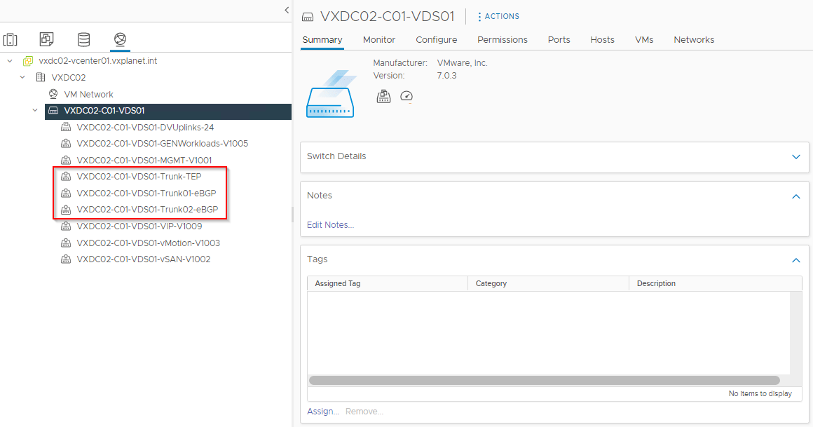
vCenter VDS Port groups
We require three trunk port groups on the compute / edge vCenter to connect the edge datapath interfaces.
- One port group to attach the TEP datapath nics (fp-eth0 and fp-eth1). This will attach to VDS uplink1 and uplink2 in Active-Active mode.
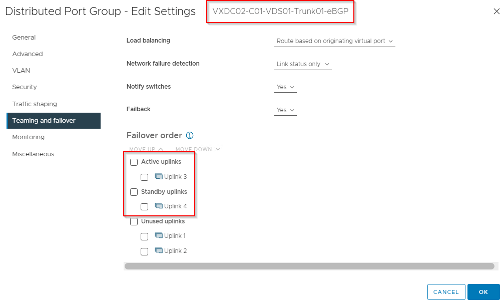
- One port group to attach edge BGP uplink1 (fp-eth2). This will attach to VDS uplink3 and uplink4 in Active-Standby mode (uplink3 Active for example).
- One port group to attach edge BGP uplink2 (fp-eth3). This will attach to VDS uplink3 and uplink4 in Active-Standby mode (uplink4 active for example).


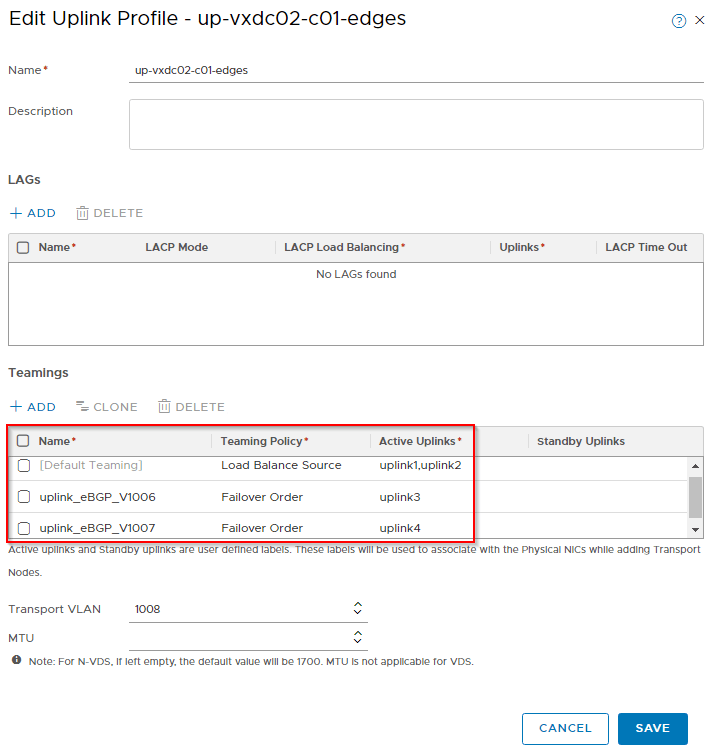
Edge uplink profile
Uplink profile defines the teaming policies and the TEP VLAN. We will define three teaming policies:
- Default Teaming policy -> This is for East – West TEP traffic (overlay) with “Load balance source” as the teaming mode and mapped to datapath interfaces fp-eth0 and fp-eth1 (Active – Active)
- Named teaming policy (uplink_eBGP_V1006) -> This is for North – South and eBGP peering with ToR switch 1 over VLAN 1006 and mapped to datapath interface fp-eth3
- Named teaming policy (uplink_eBGP_V1007) -> This is for North – South and eBGP peering with ToR switch 2 over VLAN 1007 and mapped to datapath interface fp-eth4
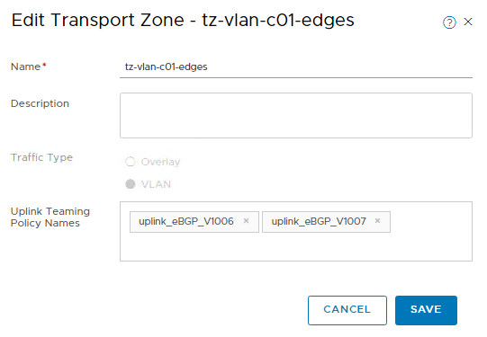
Transport zones
The two named teaming policies will now be applied to the VLAN transport zone on which the edge nodes will be a member of.
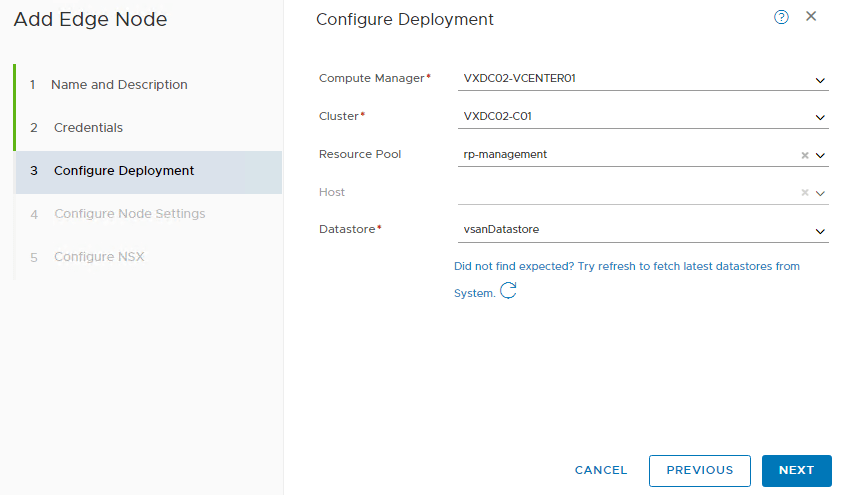
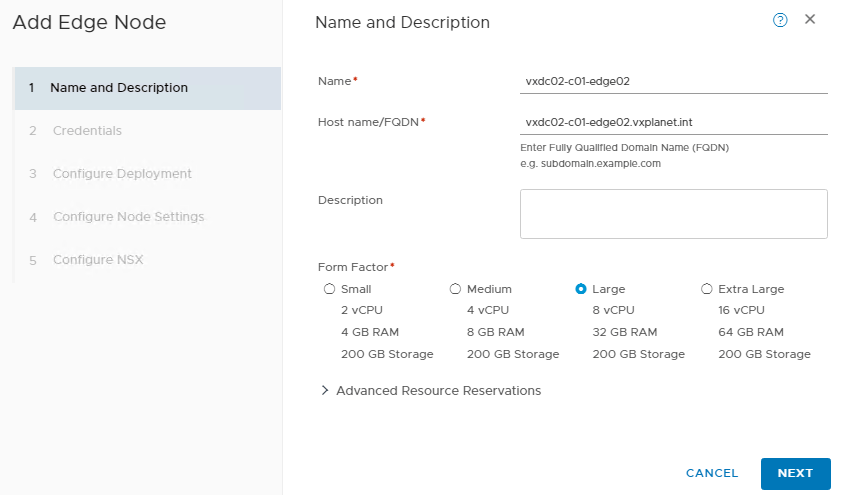
Deploying the edge node
We will next deploy two edge nodes “vxdc02-c01-edge01” and “vxdc02-c01-edge02” in Large form factor from the NSX Manager UI
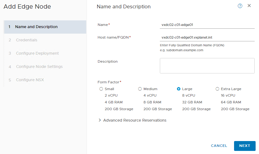
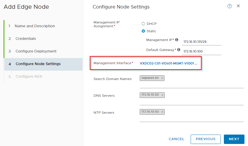
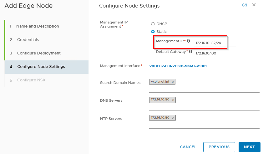
We will choose the ESXi management network as the edge node management network
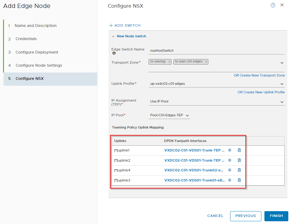
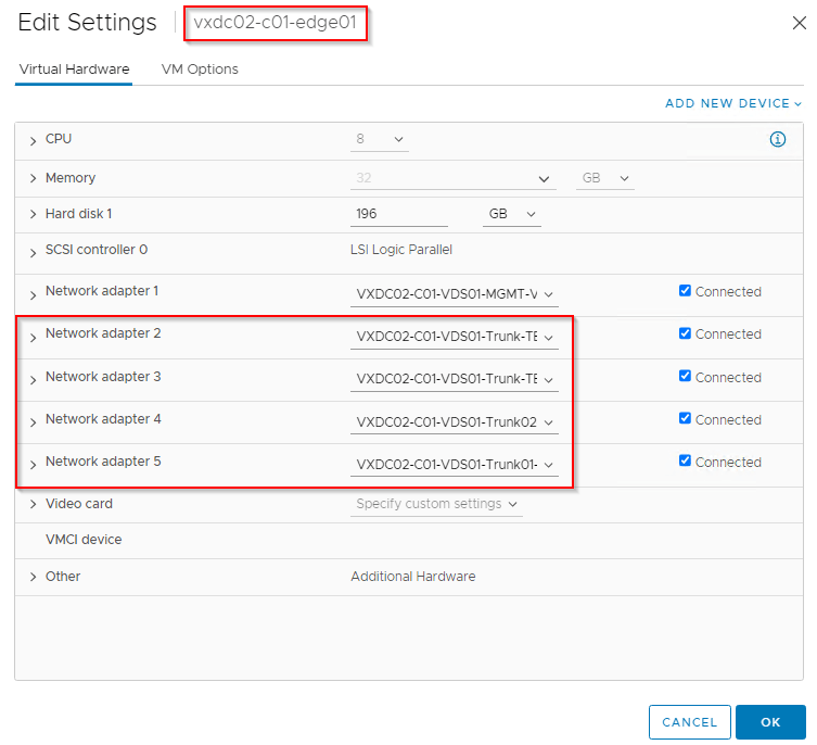
Now we map the edge NVDS uplinks to the respective VDS port groups in vCenter.
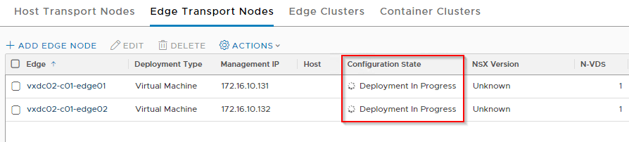
The workflow should now start the deployment of first edge node, “vxdc02-c01-edge01” in vCenter. Deploy the second edge node “vxdc02-c01-edge02” similarly but with a different management address.
Wait for the deployment workflow to complete and the edge nodes to register with the NSX management plane.
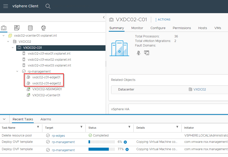
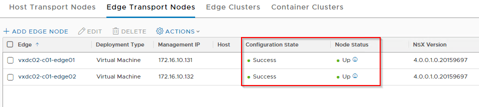
We should now see from the vCenter view that the four datapath interfaces are added correctly to each edge node.
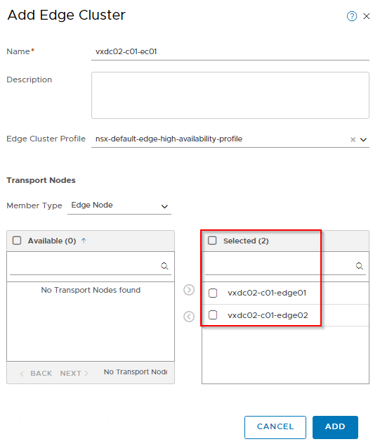
Edge Cluster
We will now add the two edge nodes to the edge cluster.
At this moment, the edge nodes are ready for consumption for data plane traffic and services. Lets verify the reachability by configuring a T0 gateway and establish eBGP peering with the ToR switches.
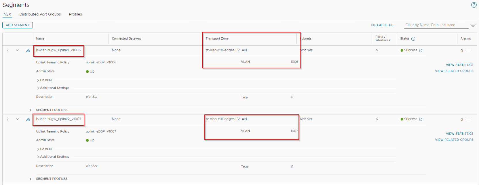
Tier0 Gateway uplink segments
We will create two VLAN segments to be used for VLAN tagging on the T0 gateway uplinks over VLAN 1006 and 1007 respectively. We will also apply the named teaming policies for deterministic eBGP peering.
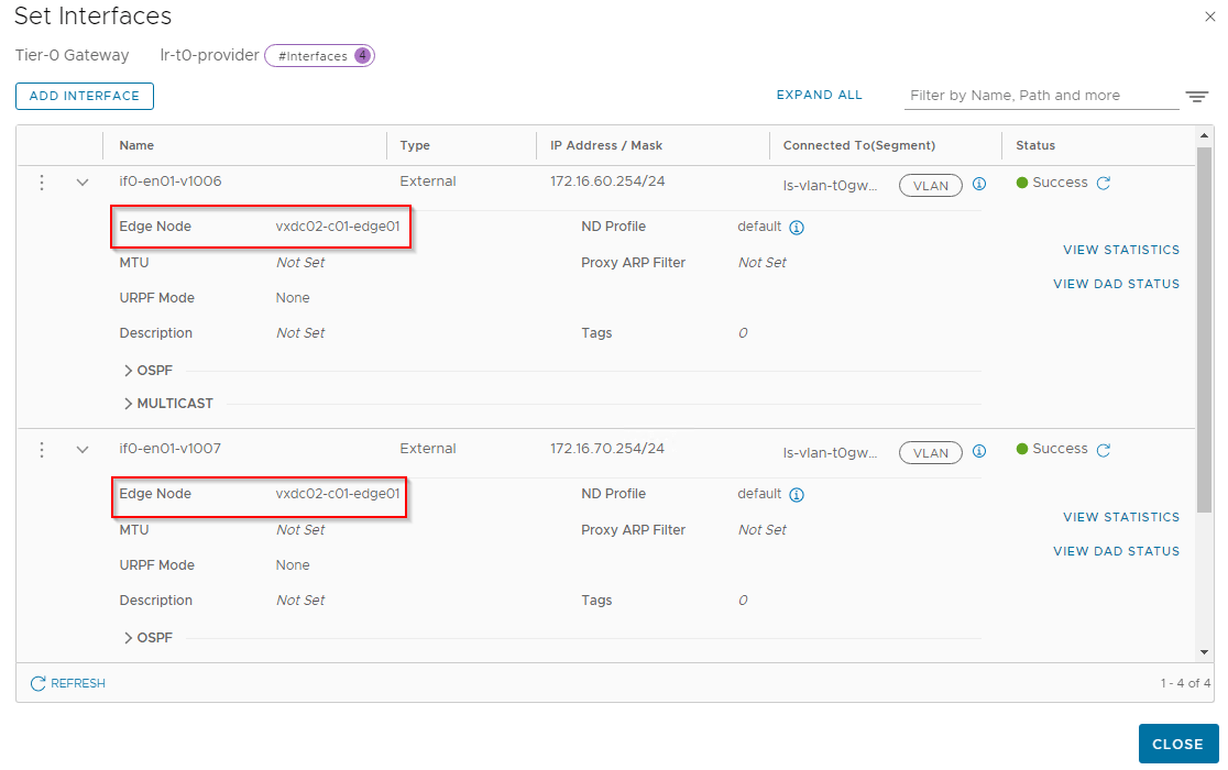
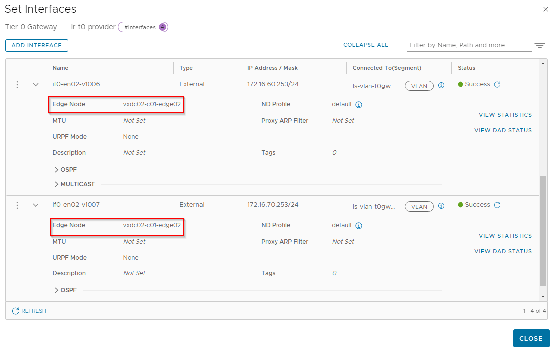
T0 Gateway
We will create a T0 Gateway with 4 interfaces – two via edge node 1 (vxdc02-c01-edge01) and two via edge node 2 (vxdc02-c01-edge02) over VLANs 1006 and 1007 with the appropriate interface uplink segments attached.


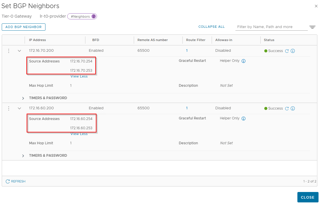
Let’s configure eBGP peering with the ToR switches (Mikrotik router in my case) over VLANs 1006 and 1007. Ideally we will establish peering over VLAN 1006 with ToR1 and peering over VLAN 1007 with ToR2.

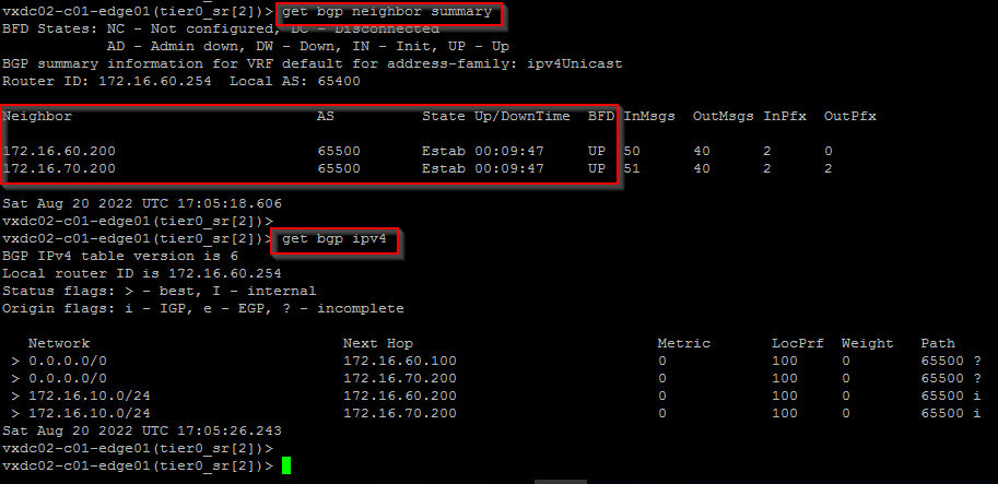
Lets login to the edge nodes over ssh, switch to the T0 SR Construct VRF and verify that BGP peering has been successfully established.

and finally, verifying the BGP neighborship status from the ToR switches (Mikrotik in my case).
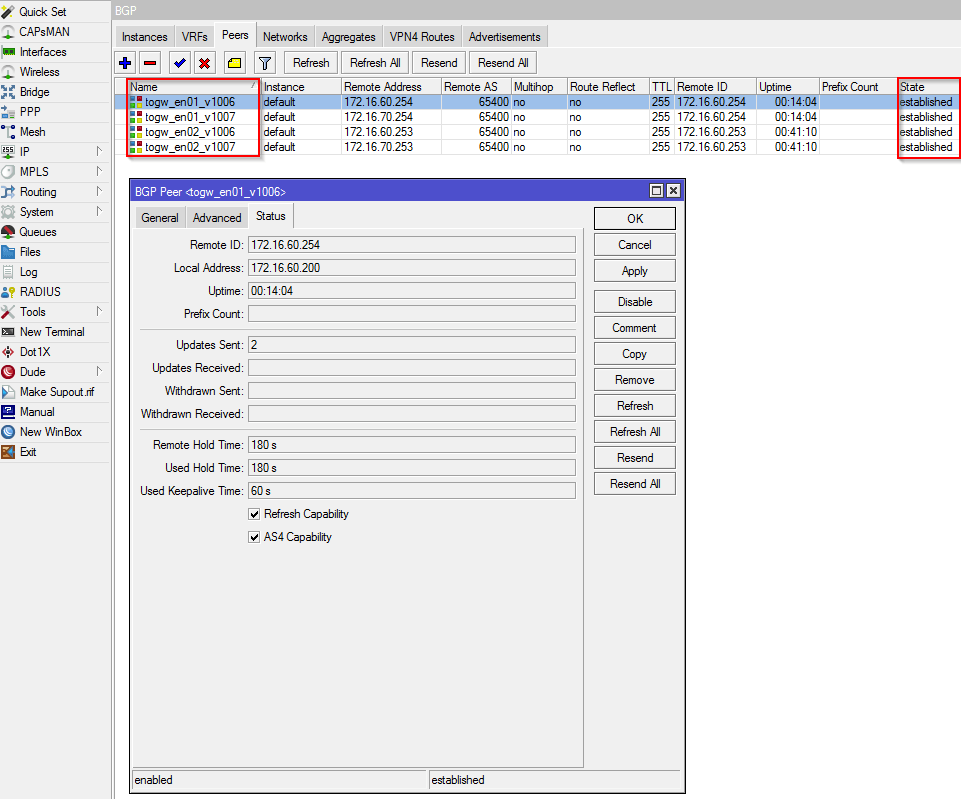
We have now successfully established North-South connectivity over the dedicated datapath interfaces fp-eth2 and fp-eth3. We can now perform basic connectivity tests for East-West and North-South flows from VMs on the overlay but this has already been covered in many of my previous posts, so lets wrap up this article.
I hope this article was informative.
Thanks for reading
diagrams are not clear. can you please create the diagrams with big blocks and fonts?
Hi Pawan, the resolution of images doesn’t fit correctly in the theme. Hyperlinks to the hires is added to each image, so you can click on an image and open in a new tab.
Thanks
Thank you for the very good work.
Very good detailed article Hari..
Thanks for the feedback.