

Welcome back and we are now at Part 4 of the blog series on NSX-T federation. In this article we will take a look at the configuration and inter-site routing of a stretched Active-Active Tier 0 Gateway with Primary and Secondary locations. If you were not following along, here are the previous parts of this series:
Part 1 : https://vxplanet.com/2021/04/13/nsx-t-federation-part-1-onboarding/
Let’s get started:
Our Topology
We will use the same topology we had in the previous article except that the stretched Tier 0 Gateway is deployed in Active – Active mode. The Tier 0 gateway has a span across all the three locations – Site A, Site B and Site C with Site A as the primary location and Sites B & C as the secondary locations. We have 5 Tier 1 Gateways attached downstream to the stretched Tier 0 Gateway.
- Stretched Tier 1 Gateway with DR only
- Stretched Tier 1 Gateway with SR (primary – Site A)
- Unstretched Tier 1 Gateway in site A only (globally provisioned)
- Unstretched Tier 1 Gateway in site B only (globally provisioned)
- Unstretched Tier 1 Gateway in site C only (globally provisioned)
We have stretched logical segments for each Tier 1 gateway:
- Segment attached to stretched Tier 1 gateway with DR only (192.168.101.0/24)
- Segment attached to stretched Tier 1 gateway with SR – Site A primary (192.168.102.0/24)
- Segment attached to unstretched Tier 1 gateway in site A (192.168.103.0/24)
- Segment attached to unstretched Tier 1 gateway in site B (192.168.104.0/24)
- Segment attached to unstretched Tier 1 gateway in site C (192.168.105.0/24)

In the above sketch, we also have a sixth Tier 1 gateway with services stretched across all the locations with T1 SR primary set to Site B. We will discuss tis scenario later towards the end of this article.
Configuring Stretched A/A Tier 0 Gateway
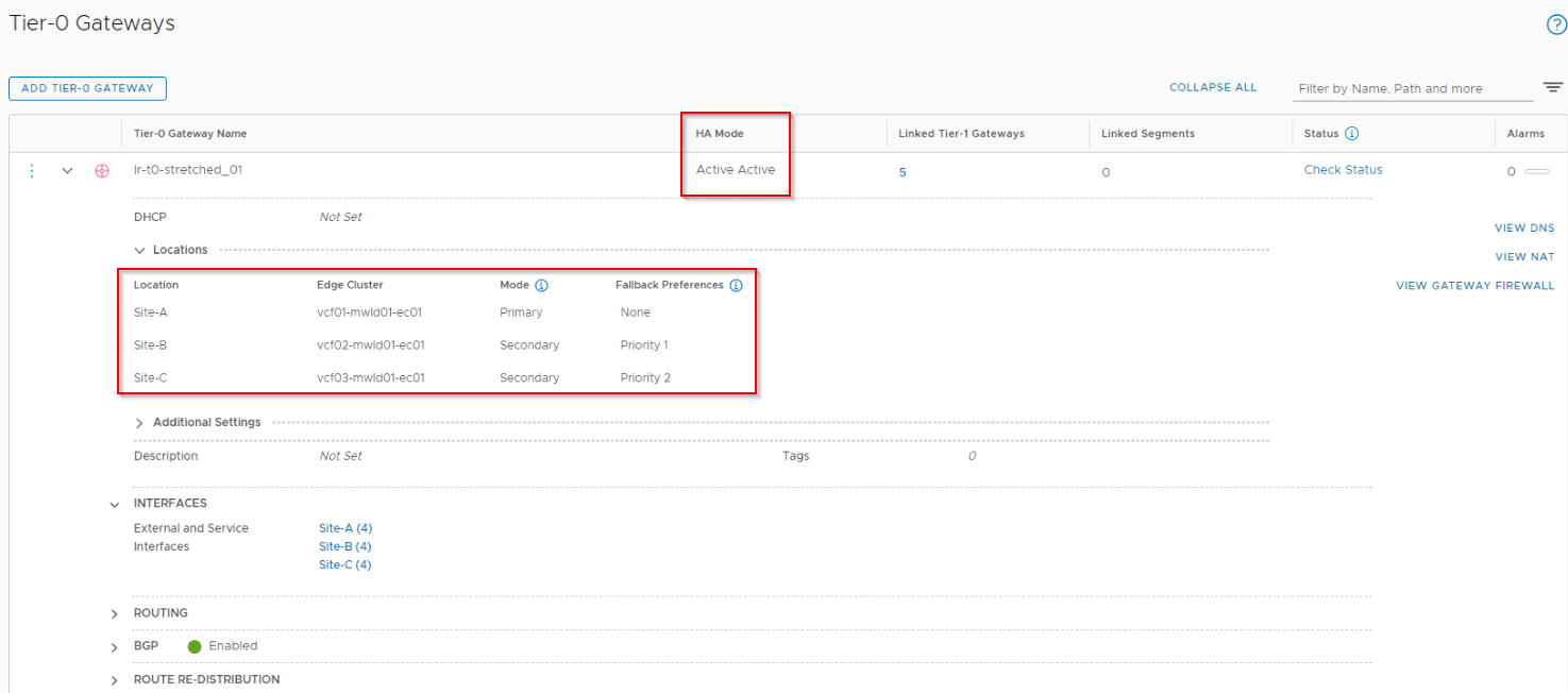
The stretched Tier 0 Gateway is deployed in Active-Active mode with span across all the three locations. As mentioned earlier, Site A is the primary and Sites B & C are the secondaries. Secondary Site B has a higher priority which will take over the primary role when Site A goes down (a manual process)
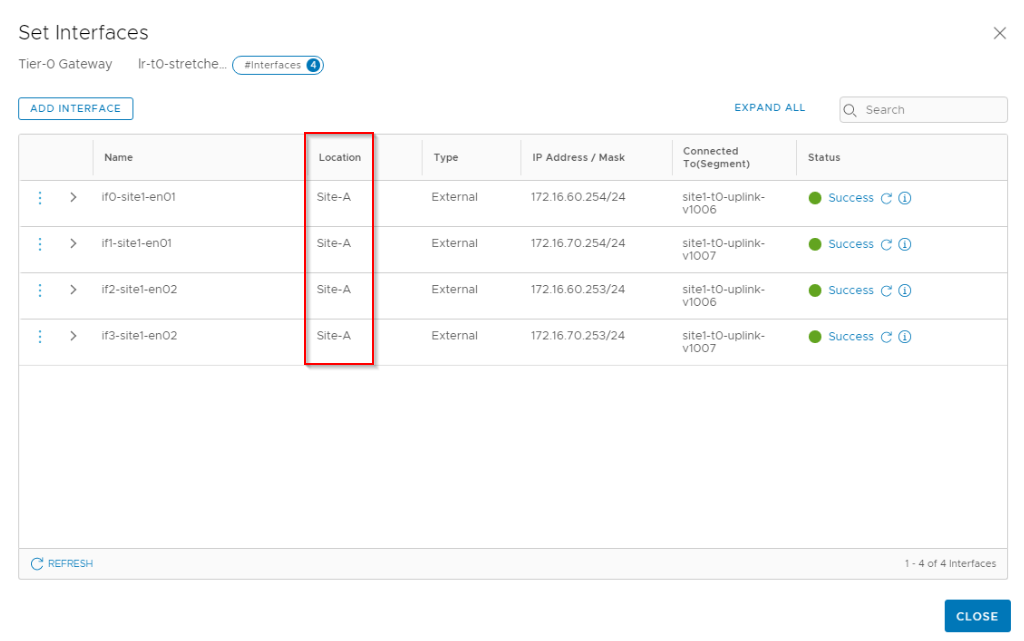
Similar to how we configured the stretched A/S Tier 0 gateway in the previous article, each location will have 4 T0 uplink interfaces attached to the respective Leaf switches. We have 3 x 4 = 12 interfaces in total. Below are the interfaces in Site A. Note that objects are realized on the local managers based on the span. For eg: Site A objects won’t appear on Site B. The IP/VLAN schema for locations were already discussed in Part 1.
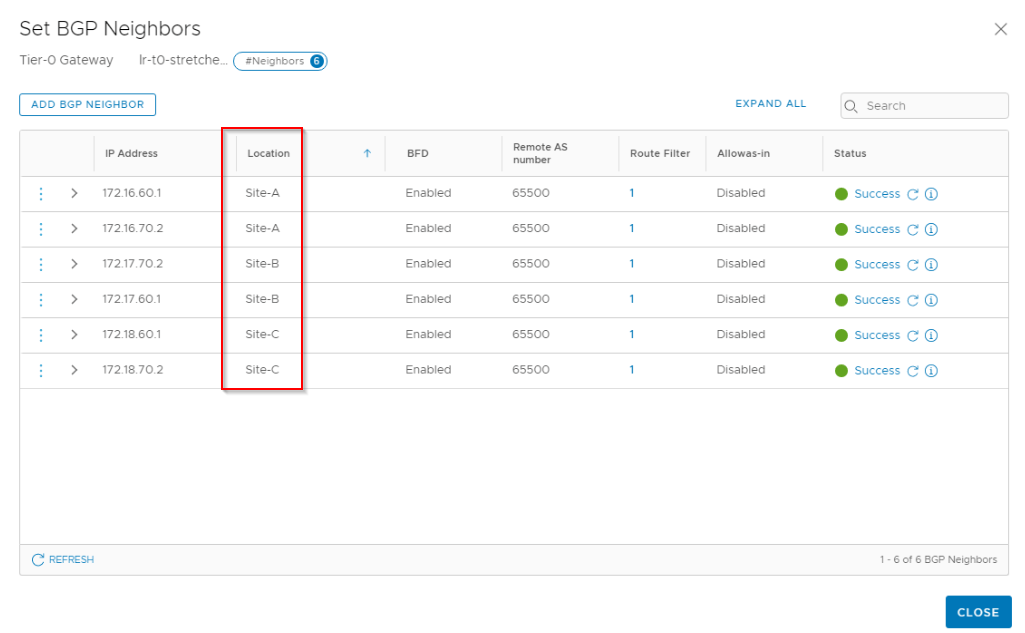
BGP neighborship between the edges and Leaf switches are established on a location basis. Note that this stretched T0 has a single ASN 65200 across locations.
Also we configured route redistribution on the Tier 0 gateway, note that this also has a span.
Configuring Stretched Tier 1 Gateways
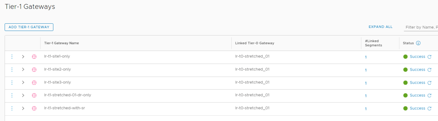
As mentioned earlier, we have five Tier 1 Gateways upstreamed to the above Tier 0 stretched gateway. These were the same T1s we configured in the previous article.
- Stretched Tier 1 Gateway with DR only – (lr-t1-stretched-01-dr-only) – Span across all three locations
- Stretched Tier 1 Gateway with SR – (lr-t1-stretched-with-sr) – Span across all locations with Site A as primary
- Unstretched Tier 1 Gateway in site A only (globally provisioned) – (lr-t1-site1-only) – Span only to Site A
- Unstretched Tier 1 Gateway in site B only (globally provisioned) – (lr-t1-site2-only) – Span only to Site B
- Unstretched Tier 1 Gateway in site C only (globally provisioned) – (lr-t1-site3-only) – Span only to Site C
Configuring stretched segments
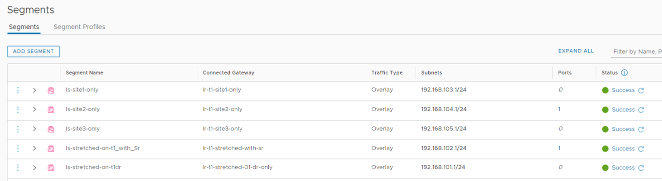
We have five logical segments each attached to separate Tier 1 gateways.
- Segment attached to stretched Tier 1 gateway with DR only (192.168.101.0/24) – ‘ls-stretched-on-t1dr’
- Segment attached to stretched Tier 1 gateway with SR (192.168.102.0/24) – ‘ls-stretched-on-t1_with_sr’
- Segment attached to Tier 1 gateway in site A only (192.168.103.0/24) – ‘ls-site1-only’
- Segment attached to Tier 1 gateway in site B only (192.168.104.0/24) – ‘ls-site2-only’
- Segment attached to Tier 1 gateway in site C only (192.168.105.0/24) – ‘ls-site3-only’
North – South routing
Primary Location
- In stretched Active-Active T0 gateway with location Primary – Secondary, both the primary location and secondary location will advertise and receive prefixes with their respective Leaf switches.
- Primary location will advertise both local as well as remote (from secondary locations) prefixes.
- Primary location is responsible for all the Northbound routing except in some scenarios where the secondary sites does the northbound routing for location specific prefixes. We will discuss that scenario later in this article.
- Inter-SR full mesh iBGP is established between the edge nodes – both with the edges intra-site as well as with edges inter-site.
- All routes received from secondary locations over the Inter-SR iBGP relationship has a reduced local preference (of 90). This gives more preference to local forwarding (and not remote forwarding) within the edge node.
- For prefixes that are not on the default VRF (learned from Leaf switches) but present in the inter-SR VRF (from secondary location), the inter-SR VRF prefixes are placed in the forwarding table. These prefixes will have next-hop pointed to the respective secondary locations. For eg: if a customer network W.X.Y.Z is reachable only via a Site B (secondary location), Site A (primary) will route traffic northbound over Site B.
- All edge nodes in the T0 edge cluster is involved in N-S routing. Scaling out of an edge cluster means increased ECMP paths.
Secondary Location
- All secondary locations establish BGP peering with the respective leaf switches, advertise and receive prefixes.
- Secondary locations advertise only their local prefixes. Remote prefixes (from primary or other secondary locations) are not advertised.
- Inter-SR full mesh iBGP is established between the edge nodes – both with the edges intra-site as well as with edges inter-site.
- For prefixes that are common on the default VRF (learned from Leaf switches) and the inter-SR VRF (from primary location), inter-SR learned prefixes are preferred and are placed in the forwarding table. These prefixes will have next-hop pointed to the primary location.
- For prefixes that are on the default VRF (learned from Leaf switches) but missing in the inter-SR VRF (from primary location), the default VRF prefixes are placed in the forwarding table. These prefixes will have next-hop pointed to the respective leaf switches.
- All prefixes received from the primary location over the inter-SR VRF will have a higher weight and local preference, so as to prefer the path over the primary location.
- All prefixes received from the other secondary locations over the inter-SR VRF will have a lower local preference, so as to prefer local forwarding and not remote forwarding.
- There is possibility that ingress to overlay networks can happen on secondary locations from their respective leaf switches. This needs to be controlled outside of NSX-T
Now let’s take a closer look at the above said routing concepts:
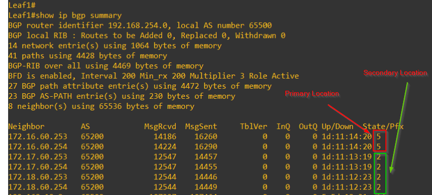
As discussed above, primary location advertises both local and remote prefixes. Secondary location advertises only it’s local prefixes. Since I am using only 2 Leaf switches for the entire federation setup, you will see all the peerings together. In reality, this is not the case.
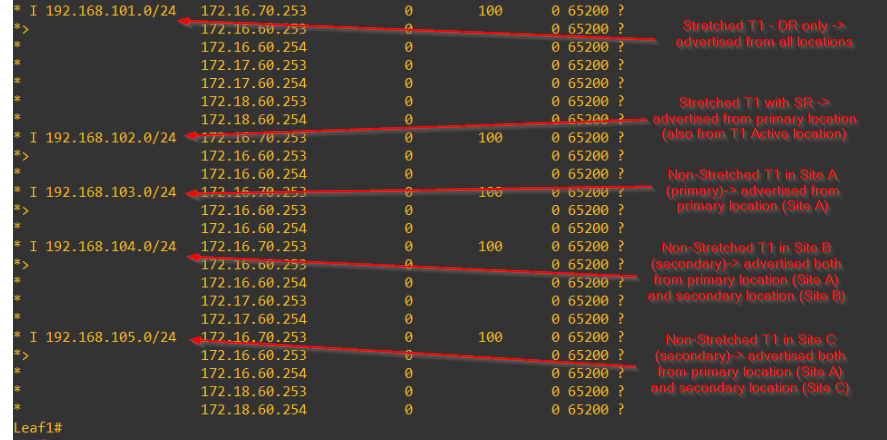
This is the BGP table on one of the Leaf switches that shows the next-hops to primary/secondary locations as per the advertisement rule we discussed earlier.
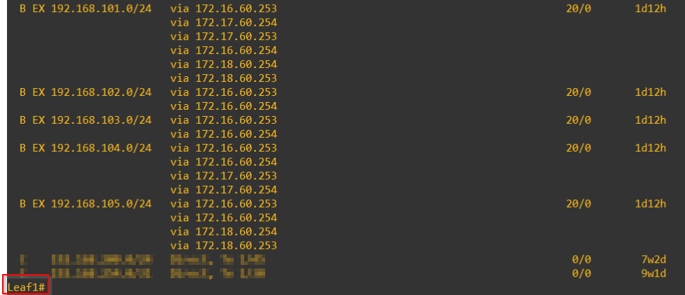
and this is it’s forwarding table.
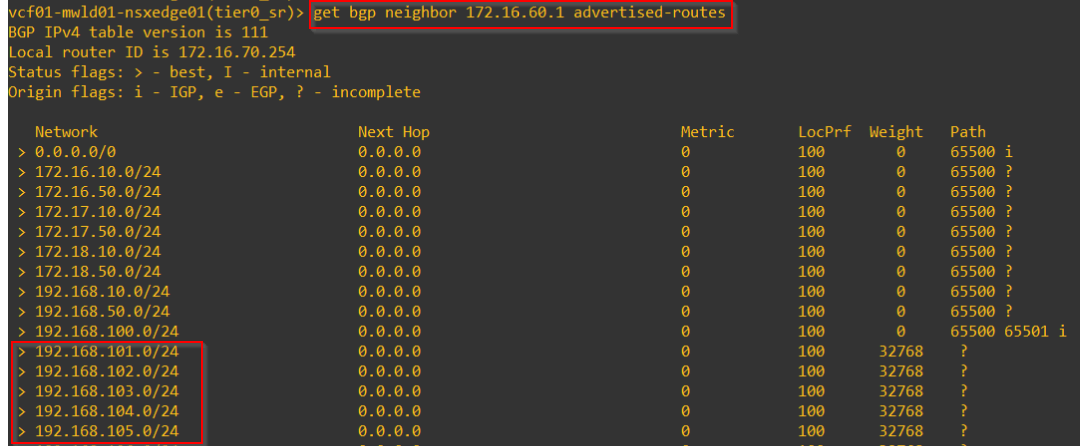
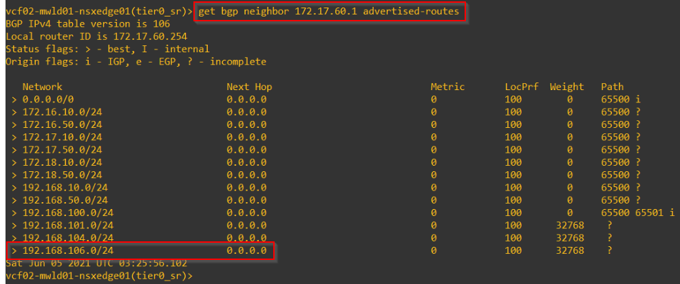
These are the routes advertised from the primary location (local + remote prefixes)
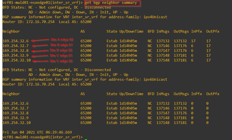
This is the Inter-SR iBGP neighborship on one of the edge nodes on the primary location. Note that unlike the previous deployment for A/S stretched Tier 0 gateway, we have peering established over to both intra-site edges and inter-site edges.
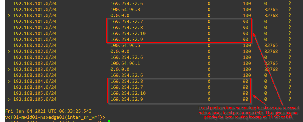
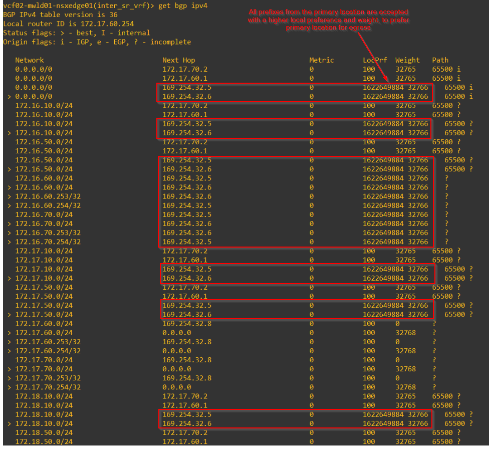
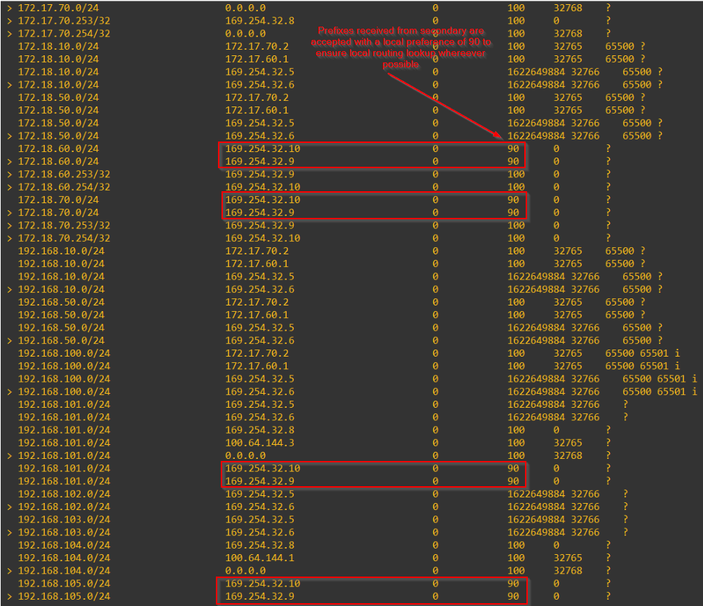
This is the inter-SR BGP table on the primary. Notice that all prefixes from the secondary locations are received with a lower BGP local preference (90). This give a higher preference for local forwarding to it’s T1 SR or DR construct from where traffic can be tunnelled based on the control plane information.
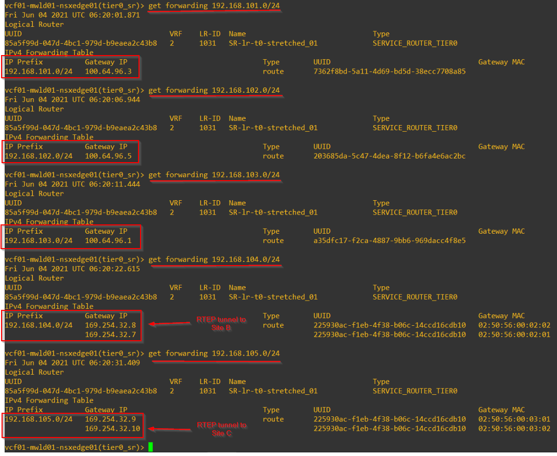
This is the forwarding table on the primary location for the five overlay segments that we created.
This is the inter-SR BGP table of the secondary location. All prefixes from primary location are received with a higher local preference and weight so as to prefer primary location for egress.
All prefixes from other secondary locations are received with a lower local preference so as to prefer local forwarding to T1 SR or DR.
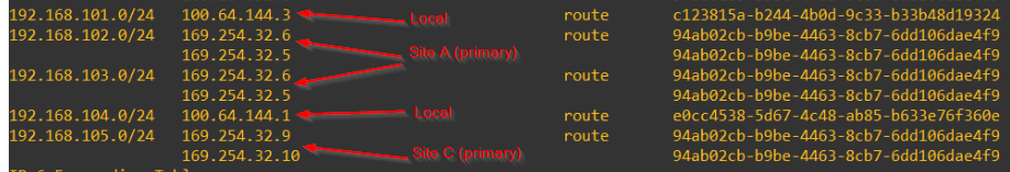
This is the forwarding table on the secondary location which shows primary location being preferred for reaching customer prefixes than it’s locally learned routes.
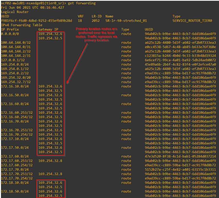
and below is for southbound overlay networks.
Scenario 1 – Northbound to location specific customer networks
Let’s simulate a scenario where primary location needs to reach customer prefixes that are specific to a secondary location. These routes are advertised from the secondary location edges to the primary location over the inter-SR iBGP. Even though our deployment topology is Primary – Secondary, we can have egress via the secondaries as well for scenarios like this.
For eg, we have a network 10.84.32.0/24 which is local to Site B.
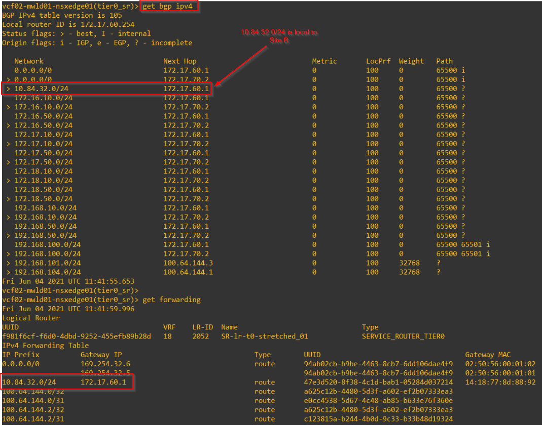
This is the forwarding table on primary location (as well as for other secondary locations too)
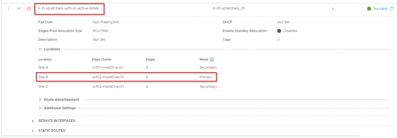
Scenario 2 – Primary location of Stretched T1 Gateway with SR not co-located with T0 Primary
Let’s create a new stretched Tier 1 gateway with SR with primary location set as Site B. The T0 primary location is Site A.
Site B now has new local prefixes, which are the services and segments attached to this stretched Tier 1 gateway.
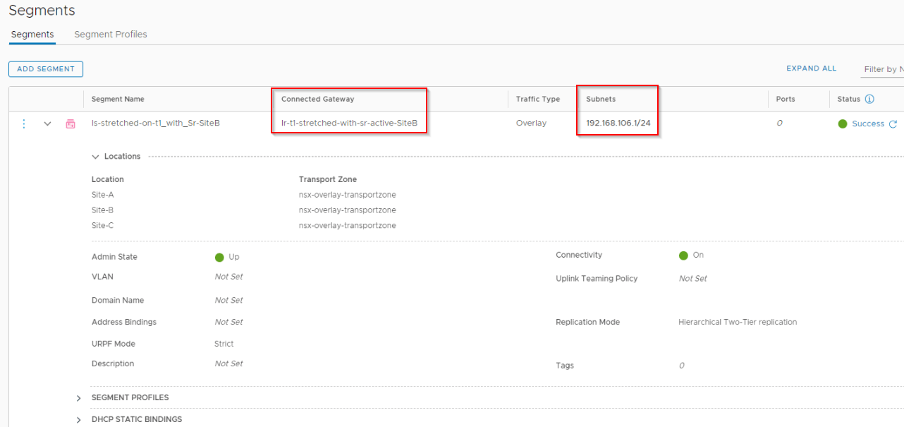
We should see that these subnets will be advertised both from Site B and Site A.
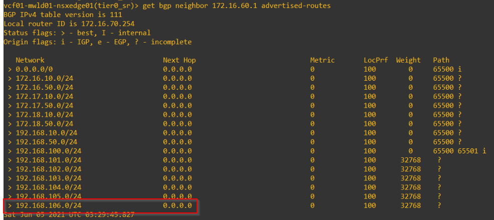
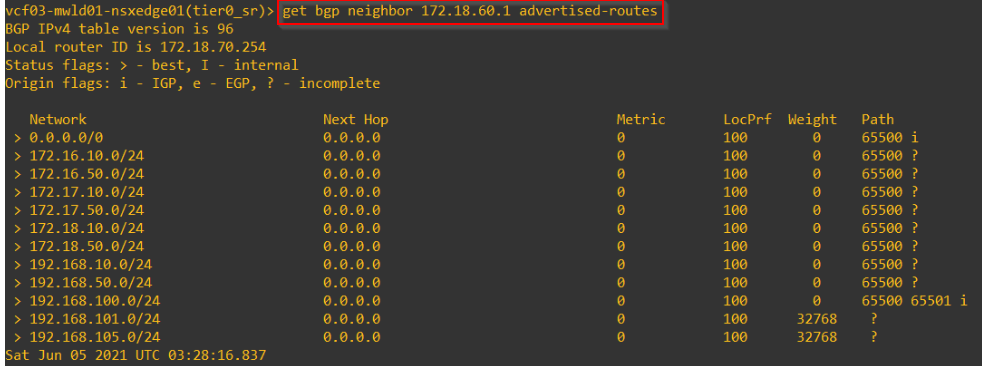
Other secondary sites (Site C) won’t advertise these prefixes.
From the leaf switches, we should see next-hops to both Site A and Site B.
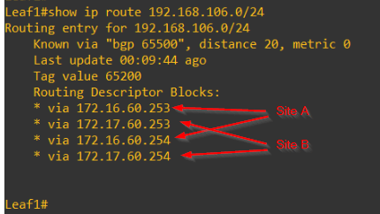
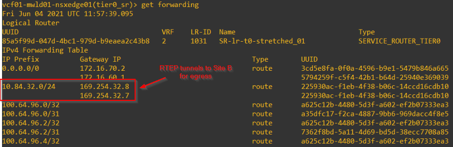
For these scenarios, be aware about hairpinning of traffic especially from a segment on Site A trying to reach external networks. Traffic is routed to Site B for T1 SR lookup and then back to Site A for T0 SR from where it egresses outside.
More on this in Part 5 where we discuss about the Packet Walk for stretched Active-Active T0 Gateway with Primary – Secondary locations.
I hope this article was informative.
Thanks for reading
Continue reading? Here are the other parts of this series:
Part 1 : https://vxplanet.com/2021/04/13/nsx-t-federation-part-1-onboarding/
Part 8 : https://vxplanet.com/2021/06/02/nsx-t-federation-part-8-tier-1-gateway-placement-considerations/
Part 9 : https://vxplanet.com/2021/06/09/nsx-t-federation-part-9-federation-control-plane-explained/
Part 11 : https://vxplanet.com/2021/06/20/nsx-t-federation-part-11-site-failures-and-network-recovery/

This is the best discussion of T0 routing that I’ve seen, and answers some routing questions that I’ve been struggling to understand. Thanks!
Thanks for the feedback, Brandon!!!