
![]()
Welcome back!!!
We are now at Part 3 of the blog series on vSphere with Kubernetes on VCF 4.0.1 Consolidated Architecture. In this article we will take a look at the TKG Compute Clusters deployed on the Supervisor Cluster namespace using the TKG Service for vSphere and CAPW (Cluster API for WCP).
If you missed the previous parts, you can find it here:
As discussed in the previous article, a Tanzu Kubernetes cluster (TKG) is a full distribution of Kubernetes platform that is built, signed, and supported by VMware. This is distributed via vCenter Content Libraries. To get the TKG Virtual machine templates, we need to create a subscribed content library and map it to Supervisor cluster namespaces where the TKG compute clusters are going to be deployed. The Virtual Machine Operator running on the Supervisor Cluster will define “vm classes” out of the virtual machine templates which is used to provision a TKG cluster as well as perform lifecycle management whenever a new version is available in the content library. Please read my previous article to know about subscribing to content libraries.
Note : TKG compute clusters are deployed in virtual machine form factor (both control plane and workers). Workload Control Plane (WCP) manages these virtual machines and vSphere DRS takes care of placement decisions.
A Tanzu Kubernetes cluster is defined in the Supervisor Namespace using a custom resource definition (CRD)

Some components included in the TKG clusters are:
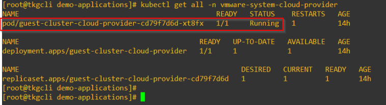
- Cloud Provider : TKG clusters run the vSphere Cloud Provider that provides integration with the NSX-T container plugin running in the underlying Supervisor cluster. All services of type ‘Loadbalancer’ is implemented as L4 VS on the NSX-T Tier 1 loadbalancer of the TKG cluster. ‘Ingress’ is currently not supported via NSX-T, we have to use a third party controller like Nginx or Contour. The cloud provider assigns a unique provider ID to each node in the TKG cluster. The pvCSI driver running on the TKG cluster depends on this Provider ID for mapping PVs to the nodes.
- CSI : TKG clusters uses paravirtual CSI plugin that integrates with the vCenter CNS through the CSI plugin in the Supervisor Cluster. The requests are delivered to the CNS-CSI of the parent Supervisor cluster, which then propagates them to CNS in vCenter Server. As a result, the pvCSI does not have a direct communication with the CNS component, but instead relies on the CNS-CSI of the Supervisor Cluster for any storage provisioning operations.
- CNI : Currently Calico is the CNI used in TKG clusters. Support for other CNI is in the roadmap. Just FYI, if you are interested to see Antrea used as CNI in TKG, please read the below William Lam’s article around this.
- There is an authentication webhook running as pod on the TKG Cluster to allow authentication tokens flow from the TKGs to the vCenter SSO via the Supervisor namespace
Creating Tanzu Kubernetes Clusters
We create TKG compute clusters by invoking the TKG Service declarative API using kubectl CLI or TKG CLI. In this article, we will focus on kubectl CLI . TKG CLI will be covered in Part 4.
Make sure the Content libraries are synced and that the Kubernetes versions are available.

Taken from the official documentation, the below chart lists the available virtual machine classes to choose from.

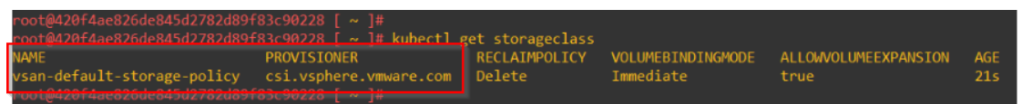
Check the Storage classes available in the Supervisor namespace.
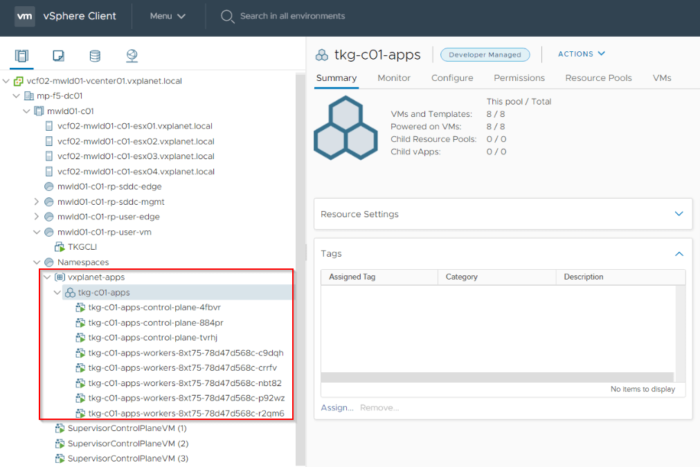
This is a sample yaml spec for the TKG cluster. Make sure to specify the correct Supervisor Cluster namespace, in our case ‘vxplanet-apps’. This will provision a TKG cluster with 3 Control plane nodes with ‘Guaranteed-large’ formfactor and 5 Workers with ‘Guaranteed-xlarge’ formfactor.
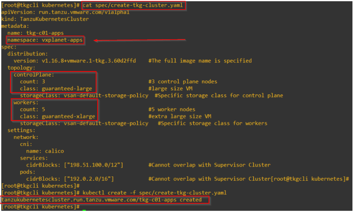
Wait for the cluster provisioning to complete.
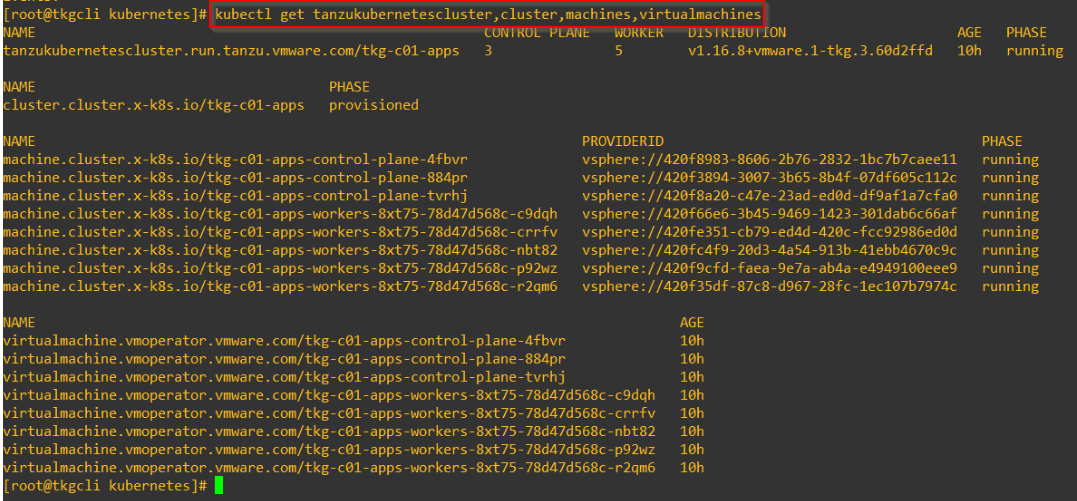
View the ClusterAPI resource of the deployed TKG cluster,

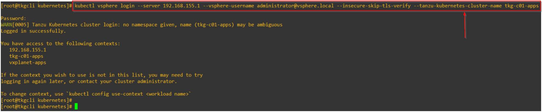
Login to the TKG cluster as the vCenter SSO user.
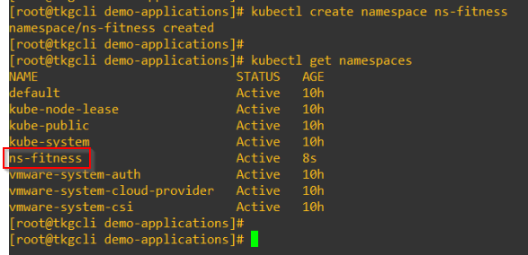
Create a TKG namespace.
By default, there is no ingress access to any workloads on the TKG cluster. We have to create a network policy to allow access.

All TKG clusters have Restrictive pod security policies (PSP) applied by default for security reasons. We have to create a RoleBinding for the user or service account to map to a Privileged PSP to be able to deploy workloads successfully. For this article let’s create a ClusterRoleBinding for all users for the same.

Deploying a Demo app on TKG cluster
Let’s now deploy a sample web app and test the access. The app is called ‘hellokubernetes’ which also deploys a Loadbalancer Service for ingress access for users. This loadbalancer service is implemented as an L4 VS on the dedicated T1 Gateway for the TKG cluster via the Cloud Provider.
Thanks to David Stamen, I am using the example apps from David Stamen’s github repo at https://github.com/dstamen/Kubernetes
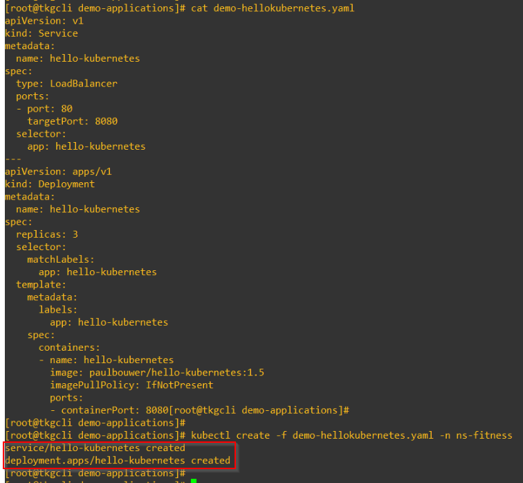
Verify that the deployment has succeeded.

NSX-T Objects Created
Taken from the official documentation, here is a summary of Endpoints and their Providers:

TKG Compute Node VMs are deployed on a dedicated NSX-T logical segment. The subnet for this logical segment is carved out of the pod cidr block defined during the configuration stage.

Each TKG cluster gets a dedicated Tier-1 Gateway provisioned in NSX-T up-streamed to the Tier 0 Gateway
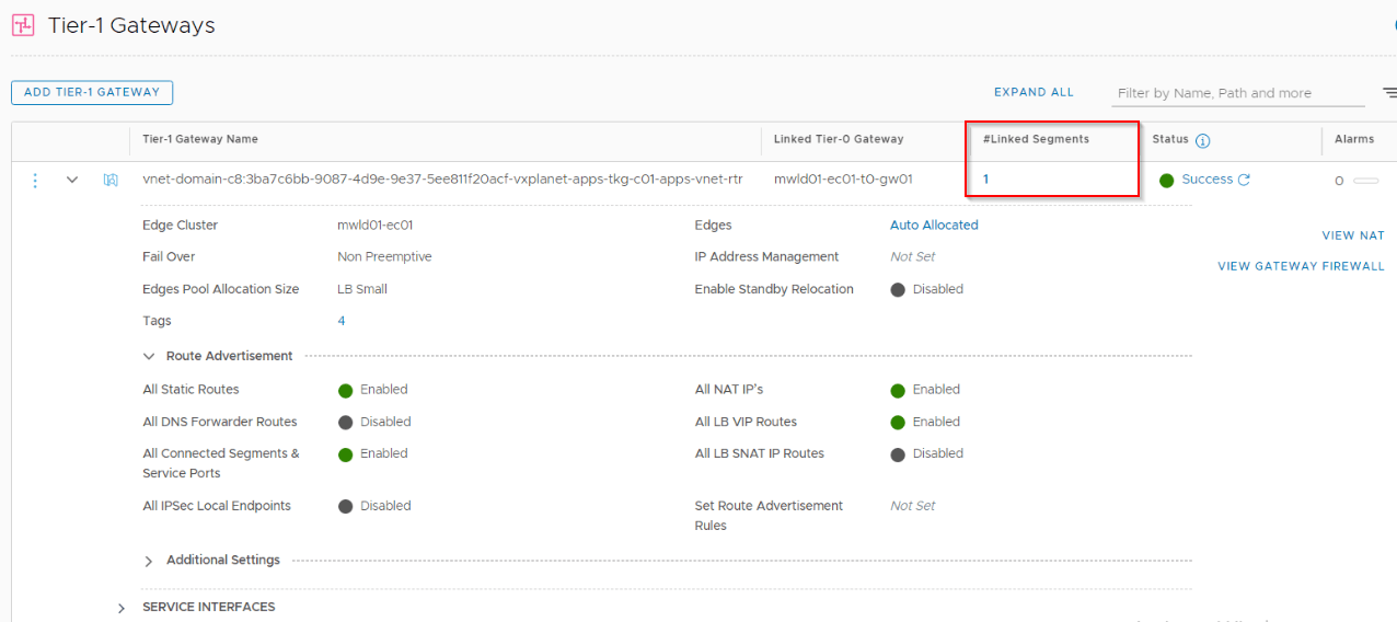
A Loadbalancer of ‘Small’ formfactor is provisioned on this dedicated Tier 1 Gateway and a L4 VS is created for handling KubeAPI requests (TCP:6443) for the TKG cluster. All VS’s use a /32 IP carved out of the Ingress CIDRs that we defined previously during the configuration of Workload management.


We could also see the L4 Vs created for the ‘helloKubernetes’ app that we deployed earlier for ingress access to the app.
Let’s try accessing the app from this VS IP.

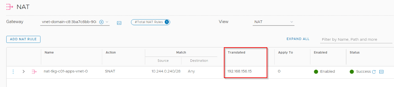
An SNAT rule is also created for egress access for the Node VMs. Calico uses the host TCP/IP stack for pod egress access which ultimately leverages this logical segment and SNAT rule for external access.
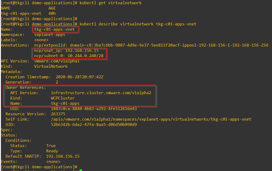
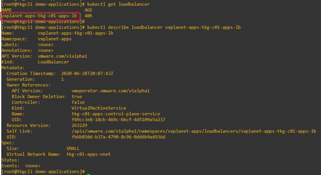
Supervisor Cluster add resource definitions (CRDs) for the virtual networks and loadbalancers provisioned for the TKG clusters and we should be able to view them using ‘kubectl’ commands under the Supervisor namespace.
Para-virtual CSI
pvCSI is the version of the vSphere CNS-CSI driver installed in the TKG compute clusters. pvCSI takes care of all storage requests for the TKG clusters. The requests are delivered to the CNS-CSI of the parent Supervisor cluster, which then propagates them to CNS in vCenter Server. As a result, the pvCSI does not have a direct communication with the CNS component, but instead relies on the CNS-CSI of the Supervisor Cluster for any storage provisioning operations. pvCSI drivers are installed and configured by the TKG service.
Taken from the official documentation, this is a quick comparison on the functionality supported by CNS-CSI on the Supervisor Cluster and pv-CSI on the TKG compute clusters:

Whenever a PVC is created on the TKG cluster, a matching PVC is automatically created on the supervisor cluster and triggers the CNS-CSI. CNS-CSI invokes the vCenter CNS to provision a PV based on the mapped Storage policies. Once a PV is provisioned, it get bound to the TKG cluster through the Supervisor namespace. As a result, we should see that the PVC in bound status on both Supervisor Cluster as well as TKG Compute clusters. Let’s confirm this.
Create a PVC on the TKG Cluster.
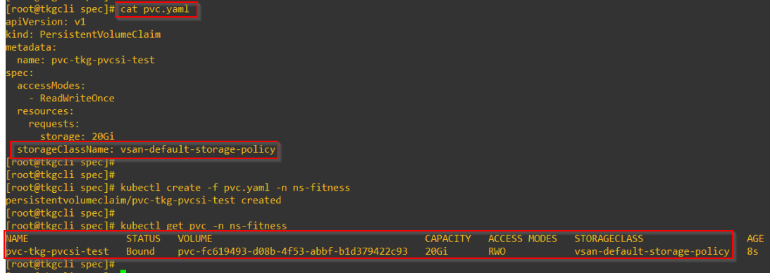
We should see the same PVC in bound status on the Supervisor Cluster namespace as well.
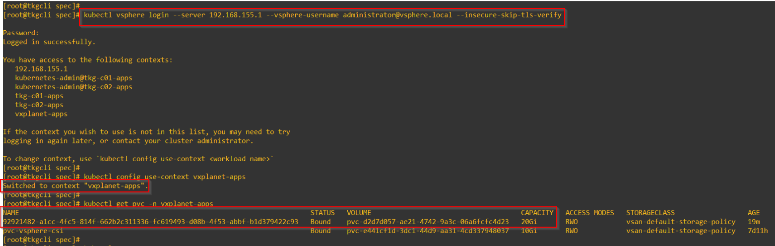
and the PV is created as an FCD on vCenter-CNS.

Scaling out a TKG Cluster
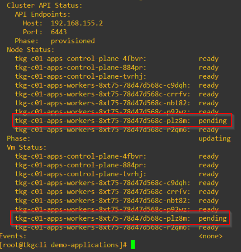
We can increase the number of worker nodes using kubectl. Only scale-out is supported, we can’t scale-in. Open the cluster manifest for editing using ‘kubectl edit’ and increase the number of worker nodes.
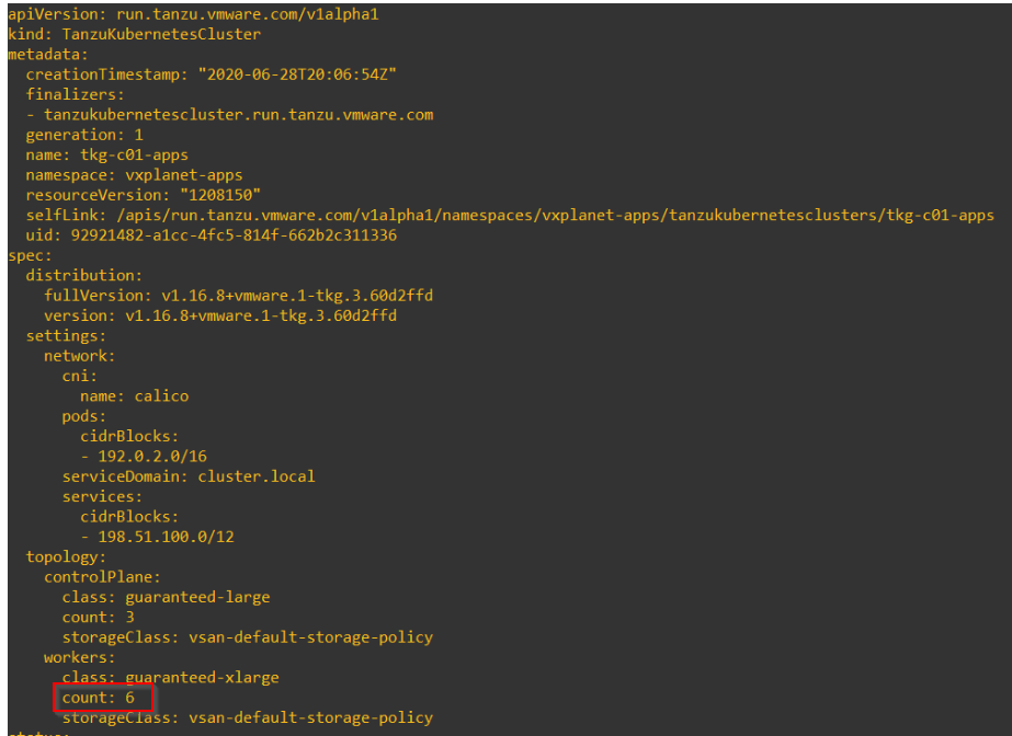
A worker VM will be deployed and will be joined to the TKG cluster.
That’s all for this blog post. We will continue in Part 4 to play with the TKG CLI utility.
I hope the article was informative.
Thanks for reading.
Continue reading? Here are the other parts of this series:

Hi Harikrishnan..thanks for this wonderful post..can you explain this part more..im still confused about what will the ips of TKG compute cluster nodes..”TKG Compute Node VMs are deployed on a dedicated NSX-T logical segment. The subnet for this logical segment is carved out of the pod cidr block defined during the configuration stage. “
Hi Dinish, while configuring Workload management, the subnet defined for the pod cidr will be used for the tkg compute cluster nodes and pods. For eg: if you have specified 172.16.0.0/16 as the pod cider in workload management, a block from that say, 172.16.0.128/28 will be used for TKG compute nodes. Thanks