
![]()
Let’s continue the blog series on vSphere with Kubernetes on VCF 4.0.1 Consolidated Architecture. This is Part 2 and we will cover the below topics:
- Walkthrough the Supervisor Cluster (TKG Service and CAPI/CAPW)
- NSX-T Objects created
- NSX-T Tier-0 Considerations
- Content Library Subscription
- Tenancy model and Supervisor Namespaces
- Storage Classes and CNS-CSI
- Accessing CLI tools and deploying a sample Native pod.
If you have missed Part 1, here is the link:
Let’s get started:
The Supervisor Cluster
Once the Workload Management feature is enabled, a Kubernetes Control Plane is created in the hypervisor layer. It transforms the vSphere Cluster into a Kubernetes cluster called the Supervisor Cluster where we run workloads as native pods or create upstream Kubernetes clusters through the TKG Service and run the containerized workloads inside these TKG Clusters.
A Tanzu Kubernetes cluster is a full distribution of Kubernetes platform that is built, signed, and supported by VMware. The Supervisor Cluster is the management plane for the TKG clusters provisioned by the TKG Service.
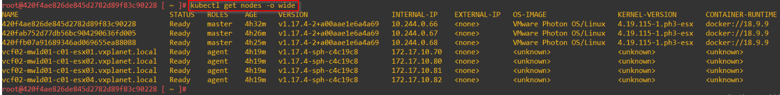
There is a one-to-one relationship between the Supervisor Cluster and the vSphere cluster. The Management WLD cluster with 4 ESXi hosts will become a 7 node Supervisor Cluster with 3 control plane VMs and 4 ESXi worker nodes.
Workload Control Plane (WCP) manages the Control plane VMs and vSphere DRS takes care of placement decisions.

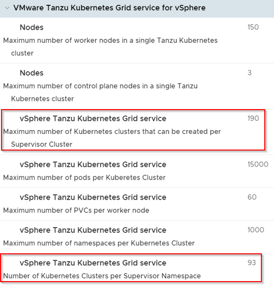
There is a one-to-many relationship between the Supervisor Cluster and the TKG clusters. We can provision multiple Tanzu Kubernetes clusters within a single Supervisor Cluster. Taken from the VMware Configuration Maximum tool, we have a limit of 93 TKG clusters per Supervisor namespace and a maximum of 190 TKGs per Supervisor cluster.
Here is the link to Configmax utility : https://configmax.vmware.com/home
Each Supervisor Control plane VM has 2 network interfaces.
- eth0 – is VLAN based that is attached to the ESXi Management network. This is where the control plane VM talks to the WCP Service, ESXi workers as well as infrastructure services like vCenter, NSX-T, CSI provisioning, DNS, NTP etc.
- eth1 – is attached to an NSX-T Overlay LS for communication with pods and deployed TKG compute clusters.
One of the Supervisor VMs is elected as a leader to talk to the ESXi workers and VLAN based infrastructure services. This node holds a floating VIP (which is taken from a pool of 5 IPs assigned during the initial configuration). The WCP Service (running in vCenter) completely manages the Supervisor Control plane VMs including migrations and lifecycle management. If a Supervisor control plane VM fails for some reason, the WCP service deploys a new Control plane VM and adds it to the Supervisor Cluster. As such, if you are dealing with a planned infra shutdown, turn the WCP service off first before shutting down the hosts.
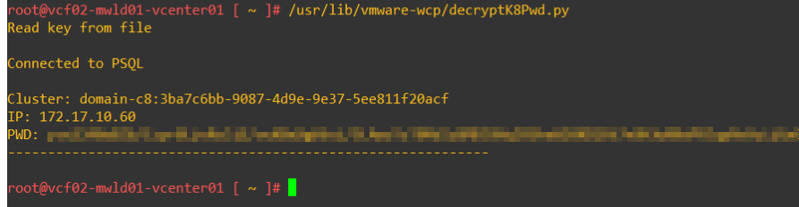
Let’s ssh to a supervisor control plane node. It’s not recommended to do so, but this is just FYI. To get the ssh password, we have to decrypt the password from vCenter:
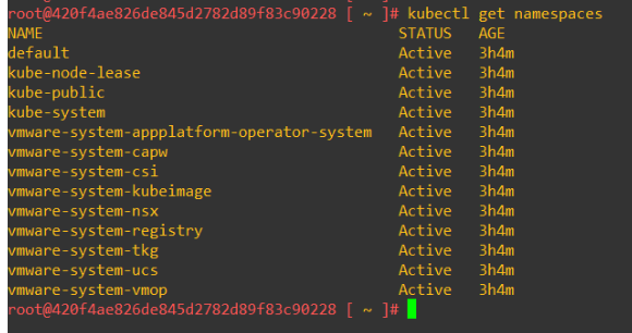
Below are the control plane namespaces. All control plane pods run only on the Supervisor control plane VMs. They are NOT native pods.
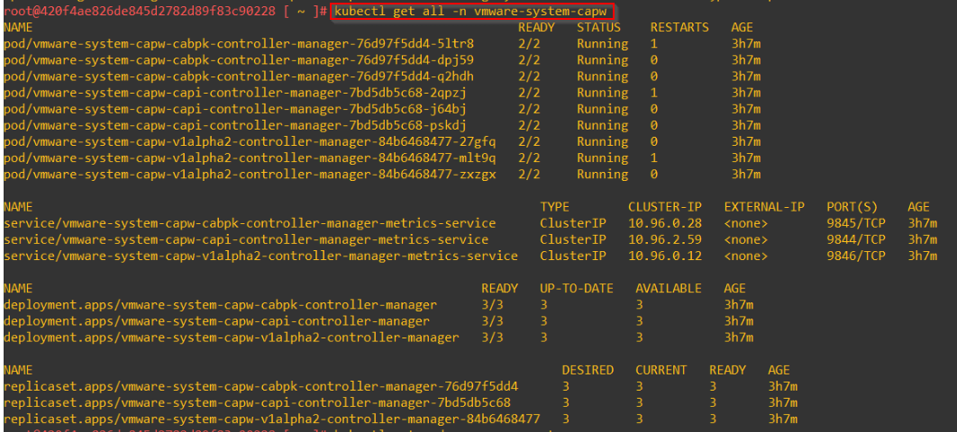
As discussed earlier, the Supervisor Cluster is the management plane for the TKG clusters provisioned by the TKG Service. It runs the TKG Controller service, Virtual Machine Service and Cluster API for WCP (CAPW) that enable the provisioning and management of TKG Compute ckusters.
- TKG Service provisions the necessary control plane components on the TKG Clusters to integrate with the underlying Supervisor namespace resources. For eg:
- An authentication webhook running as pod on the TKG Cluster to allow authentication tokens flow from the TKGs to the vCenter SSO via the Supervisor namespace
- Cloud Provider plugin in the TKG integrates with the NCP plugin in the Supervisor cluster to provision services of Type Loadbalancer on the TKGs.
- A paravirtual-CSI running on the TKGs that dynamically provisions PVs on the vCenter CNS using the Supervisor cluster CSI driver.
- The Cluster API for WCP (CAPW) provides declarative APIs for TKG cluster creation, configuration, and management. The declarative spec consists of inputs describing the cluster resources (masters/workers), virtual machine classes (small, medium, large, xtralarge) and addons (CSI, CSI, pod security policies, authentication webhooks etc)
- The Virtual machine service introduces a cluster resource called virtual machine class that describe a virtual machine hardware configuration. This functionality helps in performing lifecycle management for the TKG clusters.
Below are the capi/capw pods running under the system namespace “vmware-system-capw”
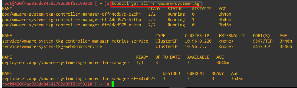
The TKG Controller pods run in the namespace “vmware-system-tkg”
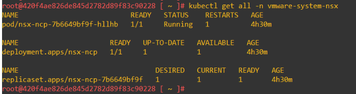
NSX-T is the CNI used in the Supervisor cluster. The supervisor cluster runs the NSX-T Container plugin (NCP) in the system namespace “vmware-system-nsx”.
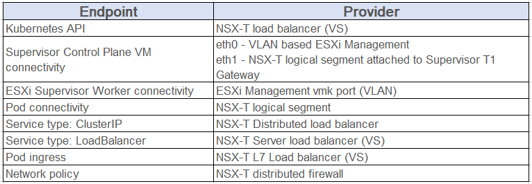
NSX-T Objects Created
This is a summary of the Supervisor endpoints and their providers:
Each Supervisor namespace gets a unique L2 Logical segment in NSX-T. For each segment, an IP block is carved out of the pod CIDR pool defined during the configuration of Workload Management.
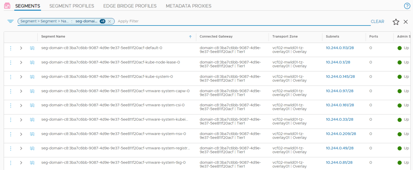
All Segments attach to a dedicated Tier 1 Gateway provisioned for each supervisor cluster. All Ingress access to pods (apps) is via Loadbalancer VIPs instantiated on this Tier 1 Gateway. A /32 IP is carved out of the Ingress pool defined during the configuration of Workload Management.
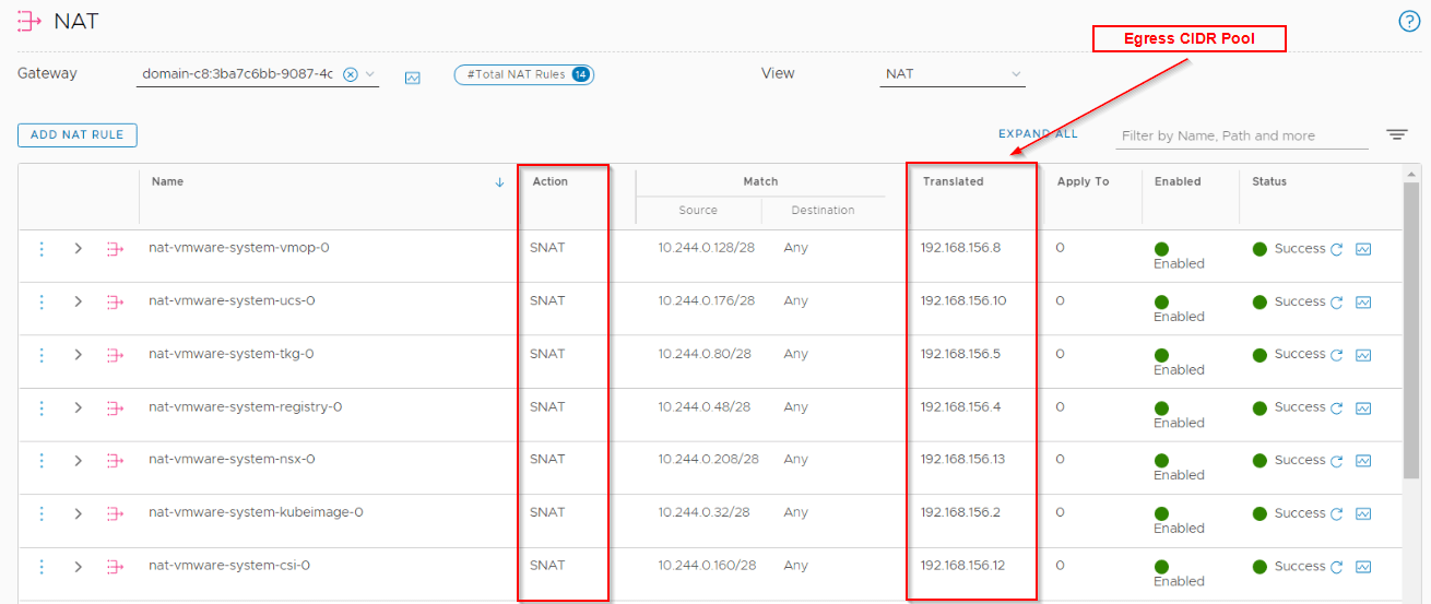
All Egress access from pods is translated to a routable subnet using SNAT rules created on this Tier 1 Gateway. A /32 IP is carved out of the Egress pool defined during the configuration of Workload Management. Each supervisor namespace gets a dedicated SNAT /32 IP from this pool.
Below are the SNAT rules created on this Tier 1 gateway for the Supervisor namespaces.
Two Loadbalancers are instantiated on this Tier 1 Gateway:
- Distributed Load balancer : All services of type=ClusterIP is implemented as distributed load balancer VIPs.
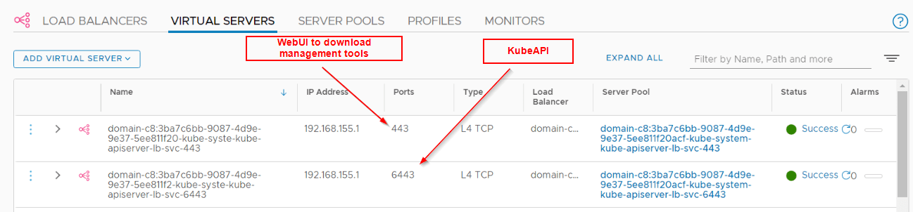
- Server load balancer : All services of type=Loadbalancer is implemented as server load balancer L4 VIPs. All ingress is implemented as L7 VIPs.
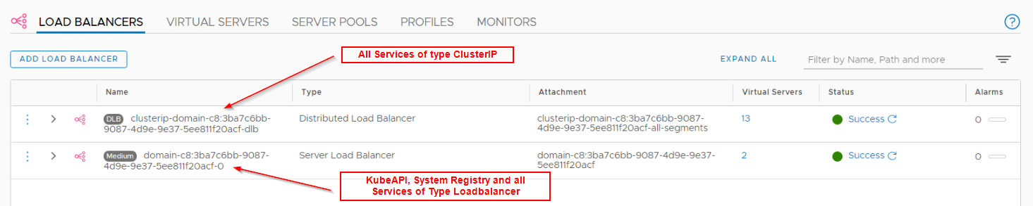
We should see two VS – one for the KubeAPI and the other for downloading the CLI tools to access the cluster.
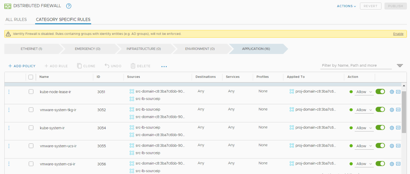
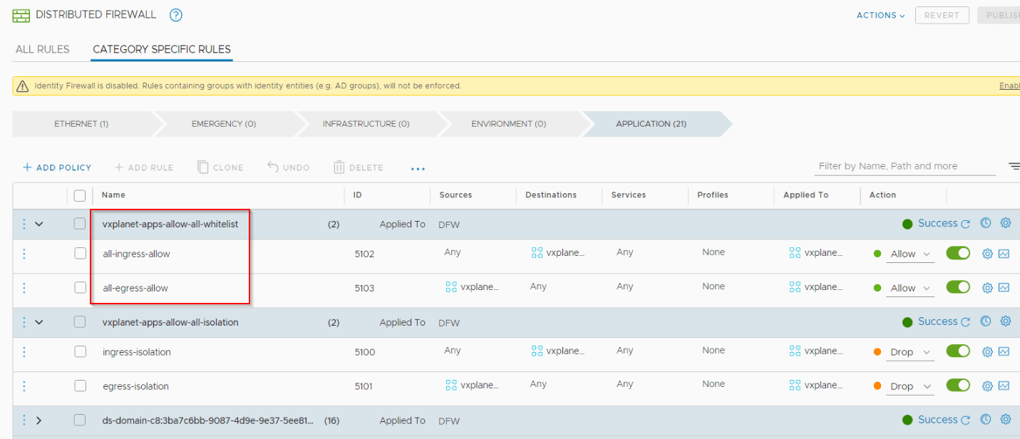
All Network policies are implemented as distributed firewalls (DFW) in NSX-T.
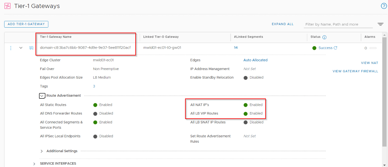
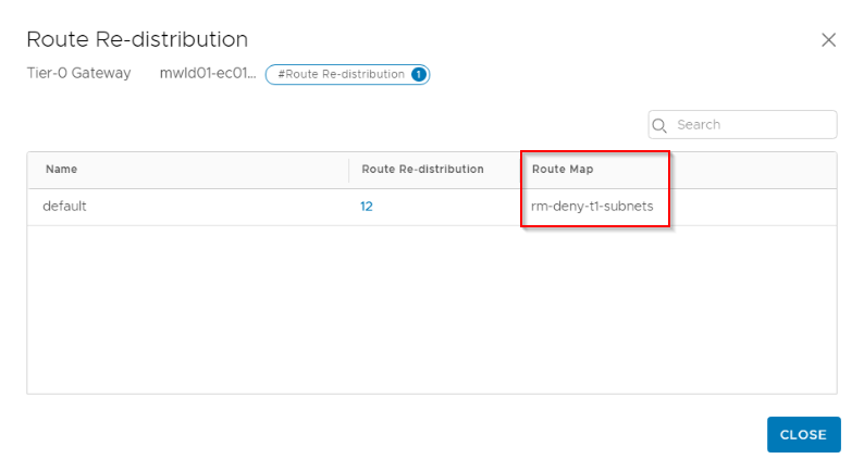
The Tier 1 Gateway attaches to the upstream Tier 0 Gateway deployed as part of AVN configuration during the VCF bring up process. As Tier 1 segments, load balancer VIPs and SNAT IPs are advertised from the Tier 1 to Tier 0 Gateway, they will be further advertised to eBGP so that these networks can be reached from customer networks. For vSphere with Kubernetes, it is not recommended to use routed pods, so make sure we have a route map specified under the BGP process in Tier 0 gateway that prevents the pod networks from being advertised. We will cover this in the next section.
NSX-T Tier 0 Gateway Considerations
- As discussed above, we don’t use routed pods, so make sure we have a route map to prevent advertising of pod networks on the Tier 0 Gateway
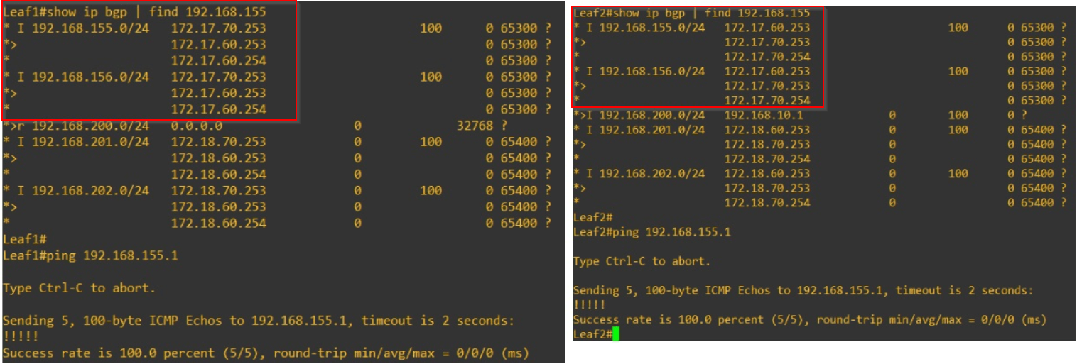
- As each load balancer VIP (Ingress) and SNAT rules (Egress) are advertised with a /32 mask, it ends up with a large number of routing table entries on the Leaf switches and networks beyond it. We need to summarize those to a classful boundary.
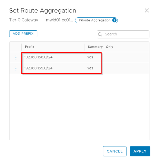
On the Leaf switches, we should now see the summarized Ingress / Egress networks.
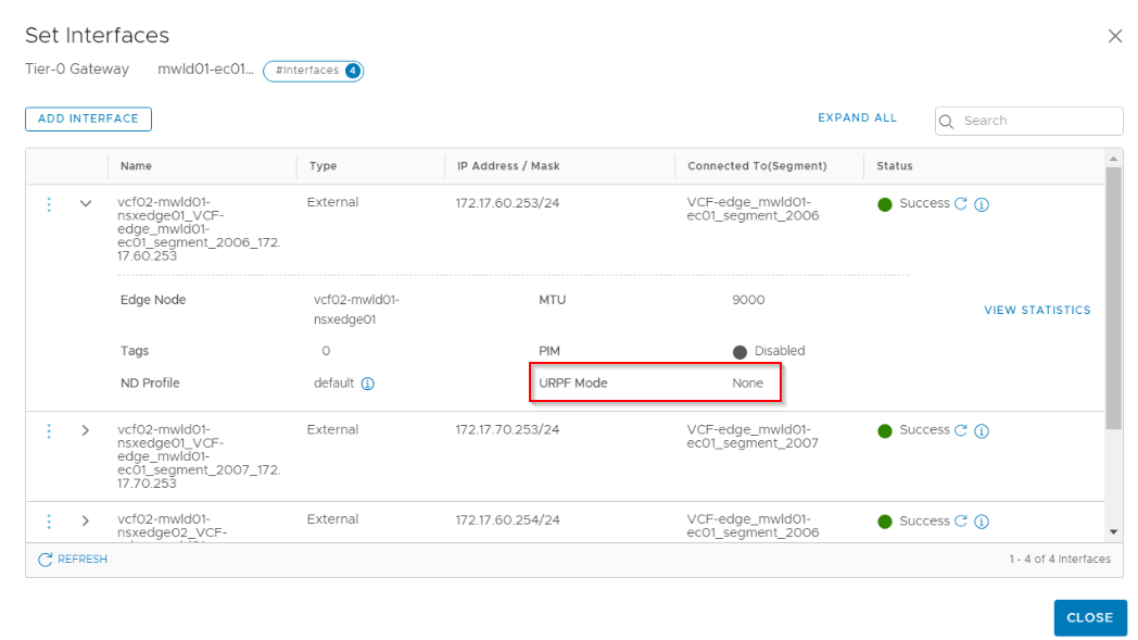
- Since ECMP routing is enabled on the Tier 0 Gateway, it is good to relax the URPF mode on the Tier 0 interfaces.
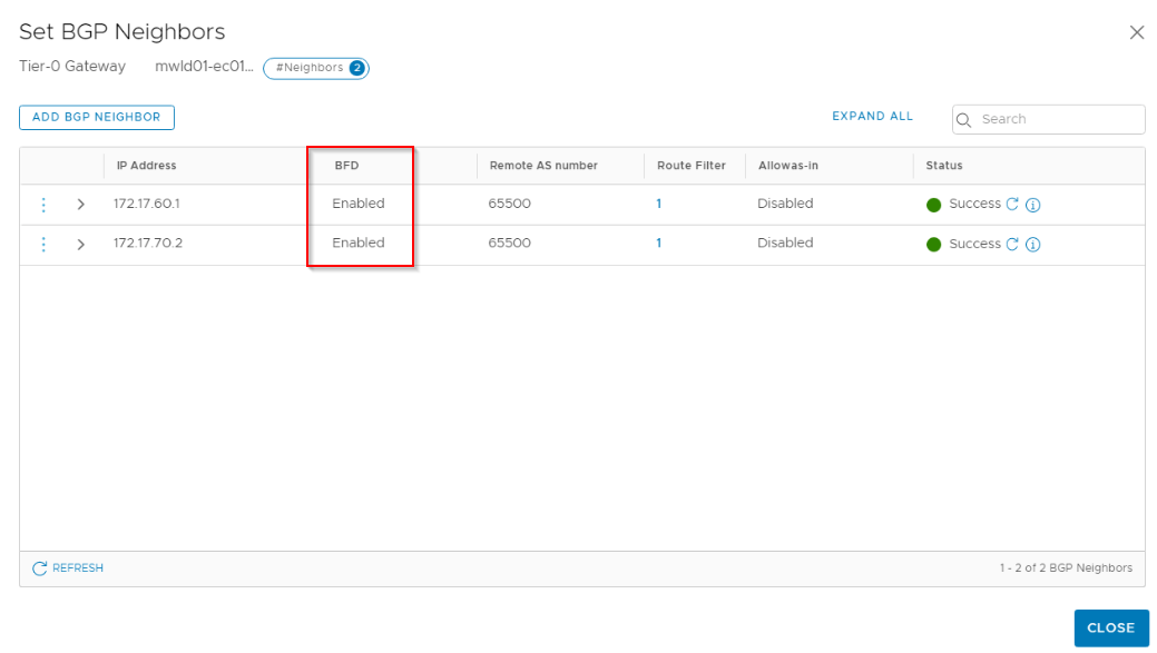
- Enable BFD for the eBGP neighbors
Content Library Subscription
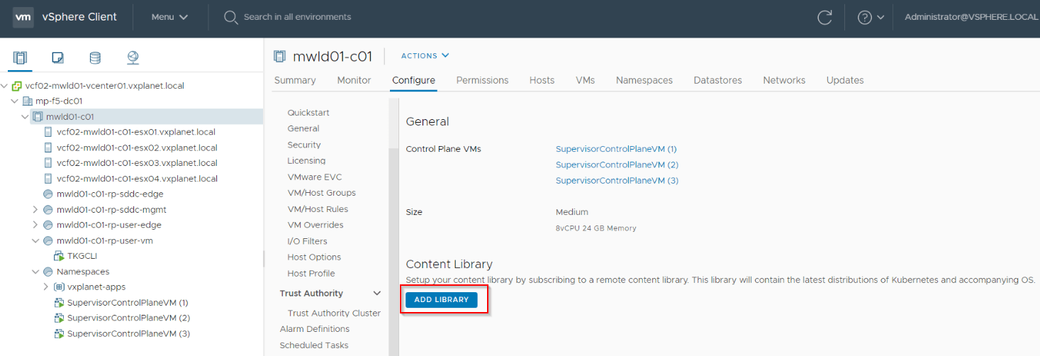
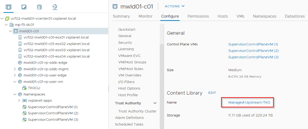
A Tanzu Kubernetes cluster is a full distribution of Kubernetes platform that is built, signed, and supported by VMware. This is distributed via vCenter Content Libraries. To get the TKG Virtual machine templates, we need to create a subscribed content library and map it to Supervisor cluster namespaces where the TKG compute clusters are deployed. The Virtual Machine Operator running on the Supervisor Cluster will see the required virtual machine images as vm classes to provision a TKG cluster as well as perform lifecycle management whenever a new version is made available in the content library.
For air-gapped environments, it is also possible to create an offline content library and manually sync it with upstream TKG versions.
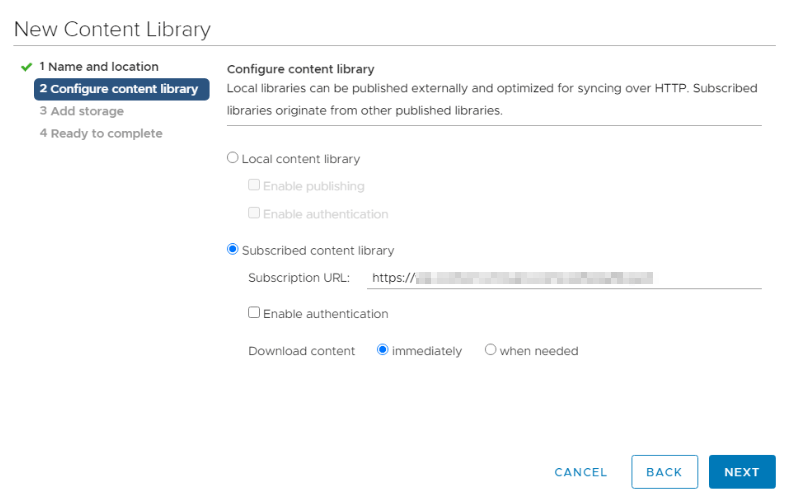
Click on Menu -> Content Libraries to create a new Content Library.


Provide the Subscription manifest URL. We can sync the library immediately or on-demand.
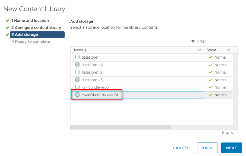
Select a storage location for the images.
Click Finish when done.

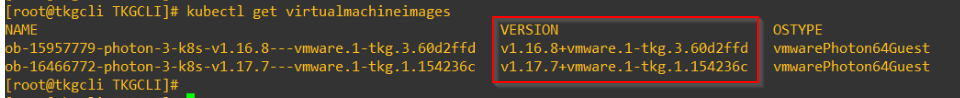
Wait for the library to sync, once completed we will be able to see ova templates for upstream TKG distribution which will be used to build the compute TKG clusters.

We can also view the available images via kubectl as CRDs for Virtual machine Operator has been already registered.
Note that the same Subscribed Content Library can be configured for multiple Supervisor Clusters. There is no relationship between the Subscribed Content Library and the Supervisor Namespace.
Tenancy model and Supervisor Namespaces
The Tenancy model is implemented via Supervisor namespaces. Each Supervisor namespace tenant can have isolation for:
- Authentication and authorization using RBAC
- Networking using network policies and NSX-T DFW
- Storage using Storage classes and vCenter Storage policies
- Deployed TKG compute clusters
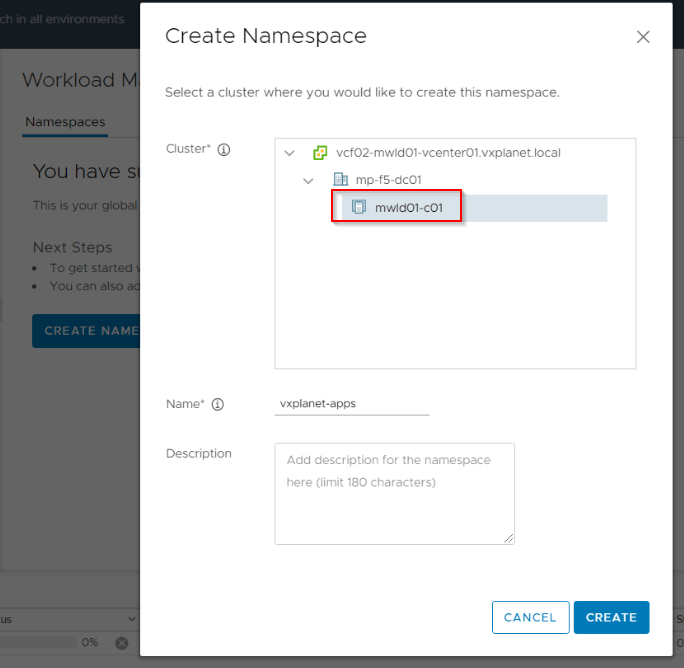
Let’s create a Supervisor namespace:
Select the Management WLD Supervisor Cluster which we have already prepared.
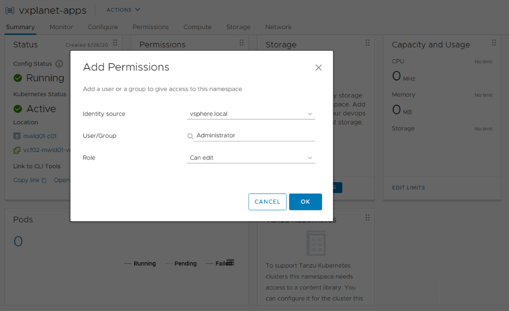
Under Permissions, select the users / groups who will have Read/Write permissions to the namespace. These permissions will be inherited by the TKG Compute clusters which we will create in Part 3 and 4. These TKG clusters will also run an authentication webhook to allow the flow of authentication tokens from the TKGs to the vCenter SSO component through the Supervisor namespace. This is taken care by the TKG Service.
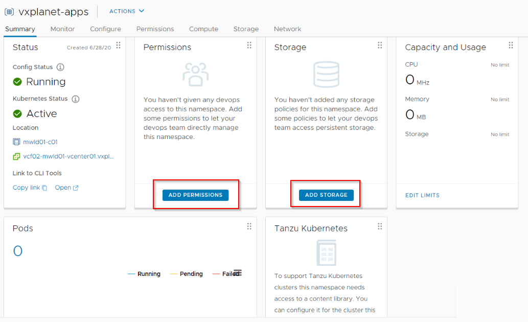
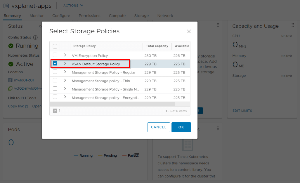
Under Storage, select a Storage Policy based on datastore requirements. This could be based on performance, size, type etc. For eg: we could have multiple storage policies that map to different LUNs based on performance tags like Gold, Silver or Bronze. For this blog post, lets use the Default vSAN Storage Policy.
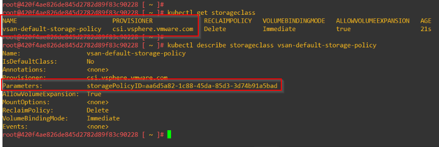
The Storage policies will map as Storage classes in the Supervisor cluster. These storage classes will also be inherited by the TKG compute clusters.
Finally map the subscribe content library to the Supervisor namespace.
Storage Classes and CNS-CSI
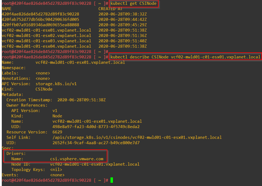
The CNS (Cloud Native Storage) component is an extension to vCenter Server that implements the provisioning and lifecycle operations for persistent volumes. The volumes are backed by First Class Disk (FCD) functionality. First Class Disk, also known as Improved Virtual Disk, is a named virtual disk not associated with a VM. First Class Disks are identified by UUID which remains same when it is relocated or snapshotted. The Supervisor Cluster interacts with the vCenter CNS for volume provisioning using the vSphere CSI plugin.
This is an example of a Persistent volume provisioned on vCenter CNS via the CSI plugin of the Supervisor cluster.
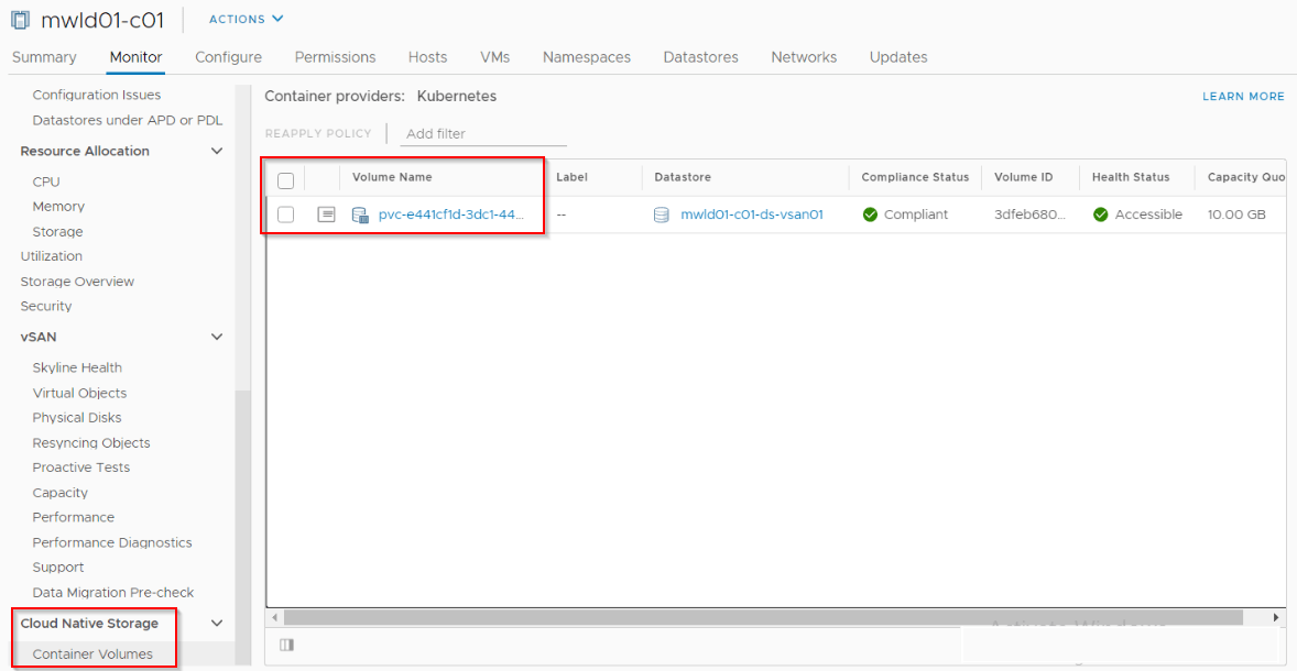
This is provisioned via a Persistent Volume Claim (PVC) using the default Storage class that is defined in the Supervisor Cluster.
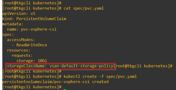
Currently the Supervisor cluster and TKG compute clusters support Only PVs with RWO (Read Write Once) mode. That means a PV can’t be shared across multiple PODs.
ParaVirtual CSI (pvCSI)
pvCSI is the version of the vSphere CNS-CSI driver installed in the TKG compute clusters. pvCSI takes care of all storage requests for the TKG clusters. The requests are delivered to the CNS-CSI of the parent Supervisor cluster, which then propagates them to CNS in vCenter Server. As a result, the pvCSI does not have a direct communication with the CNS component, but instead relies on the CNS-CSI of the Supervisor Cluster for any storage provisioning operations. pvCSI drivers are installed and configured by the TKG service.
Taken from the official documentation, this is a quick comparison between the two:
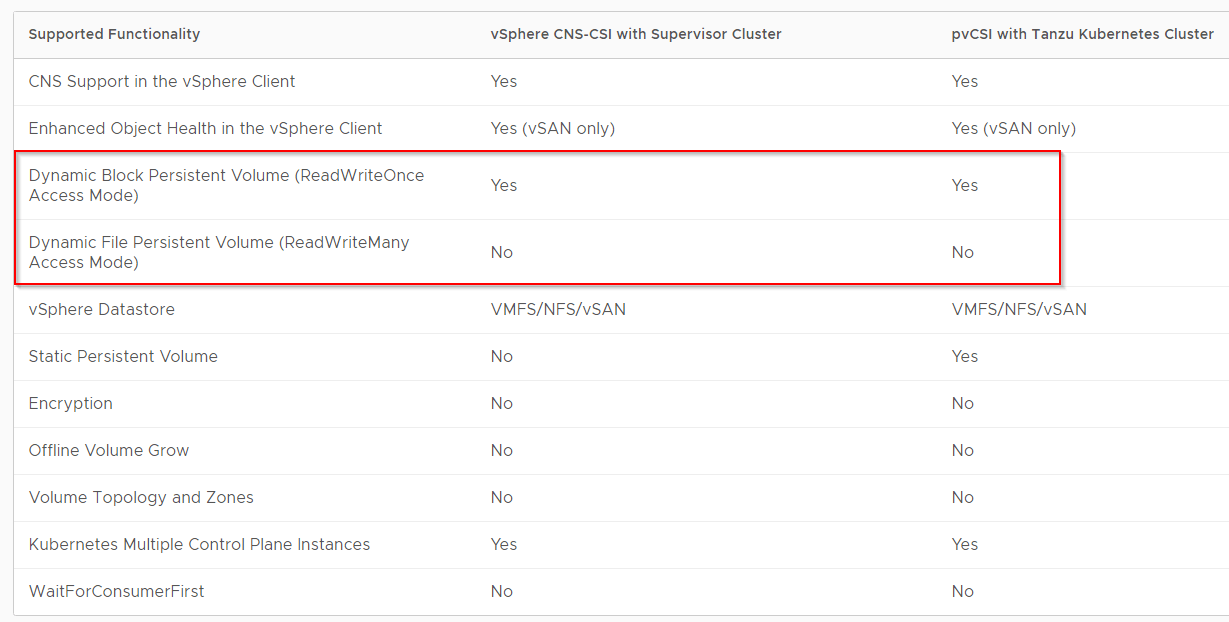
We will discuss more about pv-CSI in the next part.
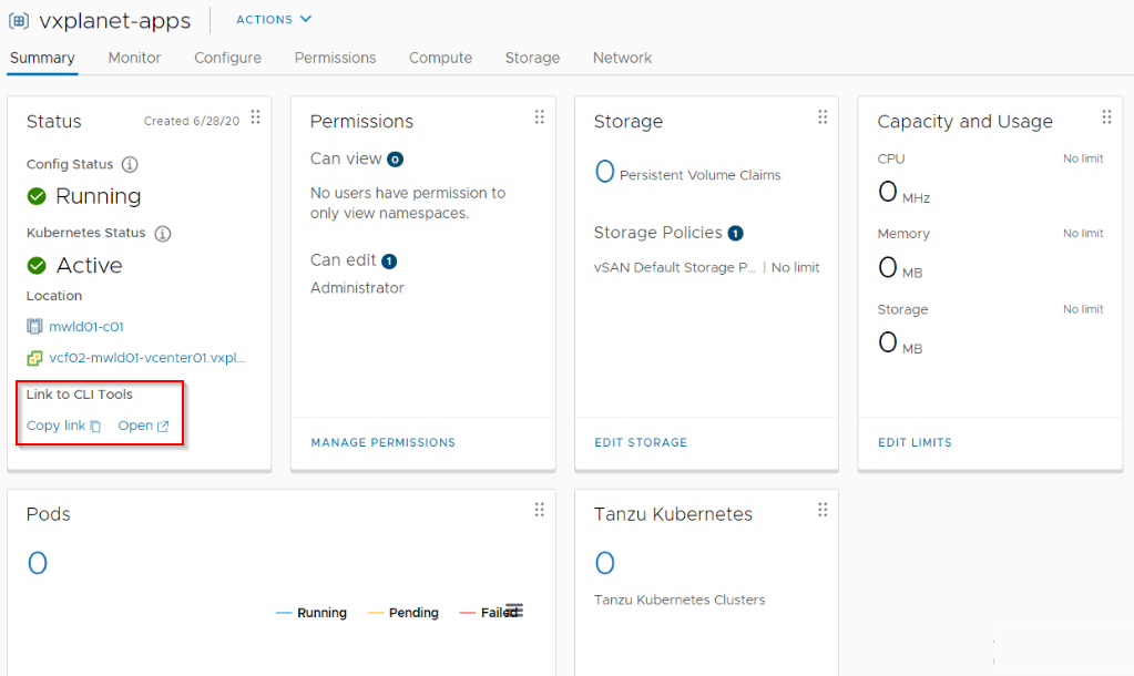
Accessing the CLI tools
The Supervisor Control plane nodes run an HTTP server from where we can download the CLI tools. This is accessible via the Tier 1 Gateway Loadbalancer VS as discussed earlier. If we are on the Workload Management Namespace view, we could also click on the link to reach the URL.
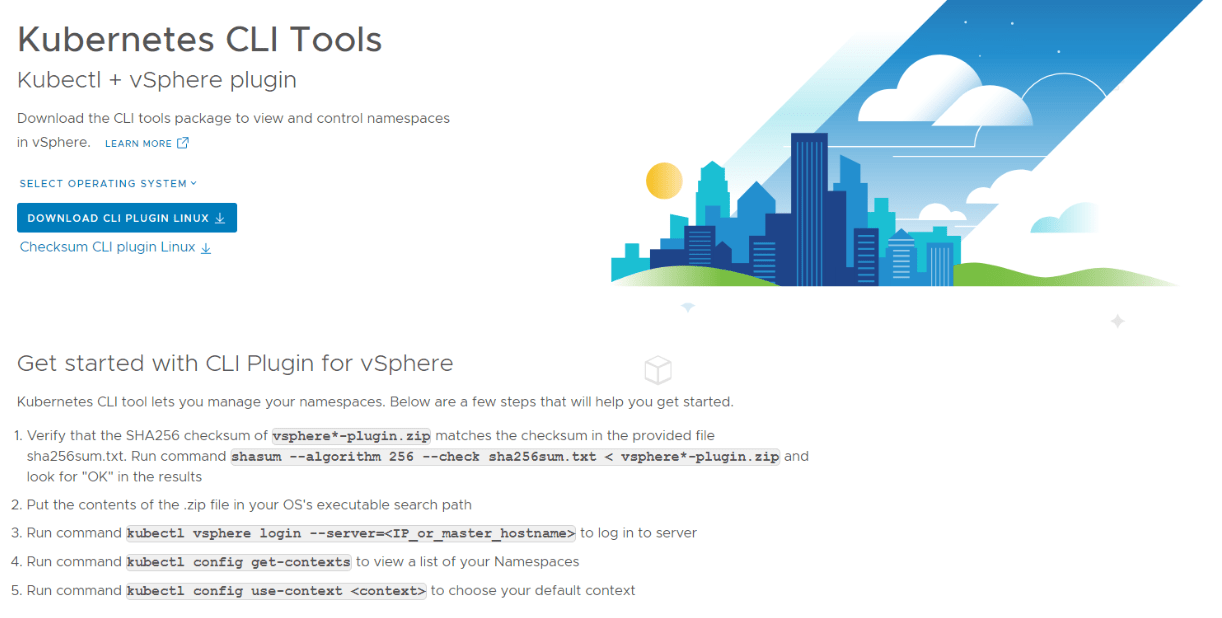
Download and install the kubectl and kubectl-vsphere utilities on an admin node based on the OS.
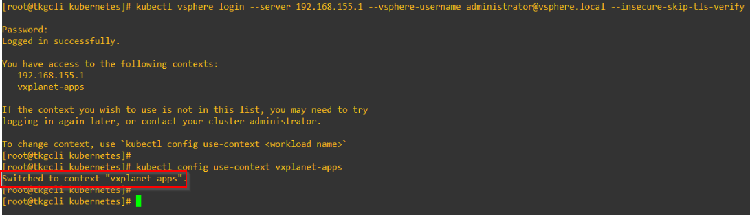
Use the ‘kubectl vsphere login’ command to authenticate against the Supervisor Control plane.
By default, there is no ingress access to any workloads on the Supervisor cluster. We have to create a network policy to allow access.
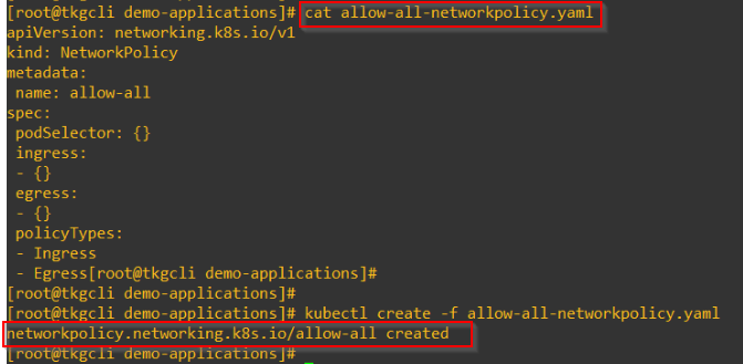
This will be reflected as DFW rules in NSX-T.
Testing a Deployment
Before wrapping up this article, lets deploy a sample nginx application as Native POD and check the status.
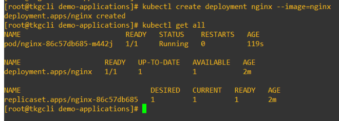
Success!!! This pod runs on one of the ESXi worker nodes directly on the hypervisor layer.
Note:
- The Supervisor Cluster has a purpose built Management Control Plane for the TKG Compute Clusters using the TKG Service and CAPW.
- We have only Namespace level privileges on the Supervisor Cluster. Root access to the Supervisor cluster is not supported.
- Third party CSI drivers are currently not supported in the Supervisor cluster as well as TKG clusters.
- Many apps nowadays comes with their own Kubernetes Operator way of deployment. As such if those apps want to register CRDs, service accounts or Cluster role bindings, it is not supported on the Supervisor cluster but only on the TKG compute clusters.
- To see when to use vSphere Native PODs and TKG clusters, please have a look at the official documentation below:
Let’s wrap-up, this has been a lengthier post, Thanks for reading.
We will continue in Part 3 to discuss TKG compute clusters.
Continue reading? Here are the other parts of this series:
Part 1 : https://vxplanet.com/2020/06/29/vsphere-with-kubernetes-on-vcf-4-0-1-consolidated-architecture-part-1/
