

Starting with NSX-T v2.4, we have a converged NSX-T manager appliance which handles the Manager, Controller and Policy API roles. We usually deploy a recommended minimum of 3 NSX-T manager instances to make up the NSX-T Management Cluster. The cluster is accessed (or consumed by CMP) via a VIP or an external Loadbalancer depending upon the deployment:
- Using Cluster VIP when the Manager nodes are deployed with L2 adjacency.
- Using a Loadbalancer as front-end when the Manager nodes doesn’t have L2 adjacency.
Cluster VIP vs Loadbalancer
- As stated above, Cluster VIP can be used only when the NSX-T Manager instances are deployed with L2 adjacency. On a typical L3 Leaf-Spine architecture without L2 stretchability across racks, this would also mean that the NSX-T manager instances have their cluster boundary at the rack level. If the Management cluster spans across racks to tolerate rack failure scenarios, NSX-T Manager instances sit on separate racks with an L3 adjacency. Cluster VIP can’t be used here, and an external Loadbalancer is needed in this scenario.
- Cluster VIP always ties to one of the NSX-T Manager instances (as Active), it does not balance the requests. This pose a scalability issue especially with few applications that generate too much API requests against the NSX-T manager cluster like Enterprise PKS running with large number of Kubernetes clusters. Enterprise PKS documentation has a recommendation to use an external loadbalancer (instead of HA VIP) if there are 25 or more Kubernetes clusters deployed.
https://docs.pivotal.io/pks/1-6/nsxt-install-mgmt-lb.html
- The load balancer VIP load balances traffic to all NSX-T Manager instances in a round robin fashion. A Cluster VIP, on the other hand, only sends traffic to one of the NSX-T Manager instances that is mapped to the Cluster IP VIP, the other NSX-T manager instances do not receive any traffic and keeps in sync with the Active instance
For this two-part blog series, lets choose a Six-node Collapsed Management, Compute and Edge cluster that is spanned across three racks in an L3 Leaf-Spine topology. There is no L2 Stretchability across racks, and the management components are deployed evenly across racks to achieve a rack failure tolerance. Here, NSX-T manager instances doesn’t have an L2 adjacency, so the requirement to use a Loadbalancer applies here.
In Part 1, we will have a look at the Leaf-Spine topology, vSphere Compute, Storage and NSX-T Networking configuration of the above-said architecture.
In Part 2, we will configure an NSX-T Tier 1 Loadbalancer for the NSX-T Management Cluster and see how the architecture survives a rack failure scenario.
Let’s get started.
Reference Architecture
This is the reference architecture for this work. This is a six-node Collapsed Management, Compute and Edge Cluster stretched across three racks in an L3 leaf-Spine BGP topology.

Leaf-Spine Networking Overview
This Leaf-Spine topology is built as per DELL EMC Leaf-Spine Configuration Guide at the below link:
Click to access dell_emc_networking_l3_design_for_leaf_spine_with_os10.pdf
Here’s a quick summary:
- Each rack has 2 X Dell EMC S4048-ON switches as leafs configured in VLT. This acts as the L2/L3 boundary for each rack.
- Leafs and Spines communicate over routed interfaces (L3) unlike traditional enhanced VLT (eVLT or MLAG) . eBGP is used as the routing protocol between Leafs and Spines. OSPF is not used, because NSX-T doesn’t support OSPF and we don’t want multiple routing protocols running on the leafs.
- Each Leaf has 2 uplinks – one to Spine1 and the other to Spine2. ECMP is enabled on the BGP process to achieve load sharing over both of the uplinks.
- Each rack is in it’s own BGP ASN. Below are the ASN details:
- Leafs on Rack 1 -ASN 65501
- Leafs on Rack 2 -ASN 65502
- Leafs on Rack 3 -ASN 65503
- Spine 1 – ASN 65401
- Spine 2 – ASN 65402
- NSX-T Tier 0 Gateway – ASN 65200
- Each rack is in it’s own subnet. This is the IP Schema assigned to each rack. A /24 subnet is carved out of this pool whenever needed. Spines do not connect to any hosts, hence no subnet is defined for the spines.
- Rack 1 – 172.16.0.0/16
- Rack 2 – 172.17.0.0/16
- Rack 3 – 172.18.0.0/16
- Each rack can reach the other rack’s networks in just one hop (Spine layer)
- Rack networks are redistributed into the BGP process via Route maps, so that only the pre-defined networks are advertised.
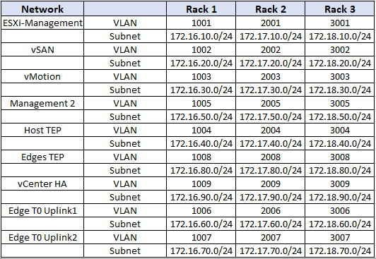
- Below is the VLAN and IP Schema of the cluster which is defined on the Leaf-Spine topology.
Compute
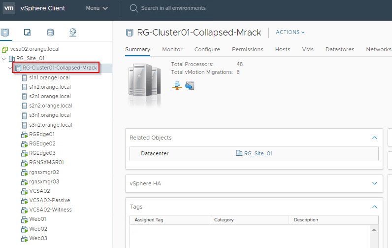
- Six hosts with two per rack to tolerate rack failure scenarios. This looks like:
- Rack 1 -> s1n1.orange.local & s1n2.orange.local
- Rack 2 -> s2n1.orange.local & s2n2.orange.local
- Rack 3 -> s3n1.orange.local & s3n2.orange.local
- vCenter HA is enabled over L3, and are deployed such that Active, Passive and Witness nodes are on separate racks. They sit on VLAN backed network and do not have cross-rack mobility. In event of Active node going down in a rack failure scenario, Passive node on the next rack takes over.
- 3 x NSX-T Managers are deployed, each on separate rack. They sit on VLAN backed network and do not have cross-rack mobility. In event of one manager instance going down due to rack failure, other two manager instances on separate racks will provide a quorum.
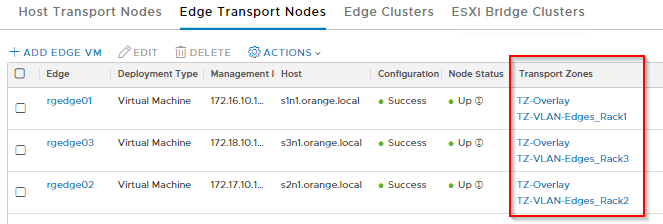
- 3 x NSX-T Edges are deployed, each on separate rack. They sit on VLAN backed network and do not have cross-rack mobility. In event of one Edge node going down due to rack failure, other two Edge nodes on separate racks will still constitute for the Tier 0 Uplinks.
- 3 x Test Web VMs are also deployed for a failover test. They sit on NSX-T Overlay network and have mobility across racks.
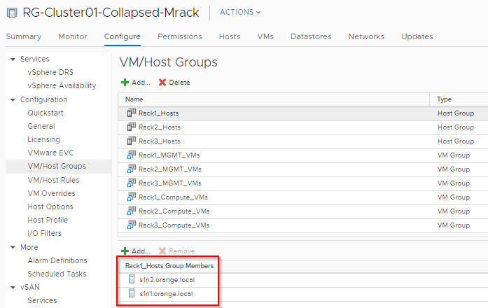
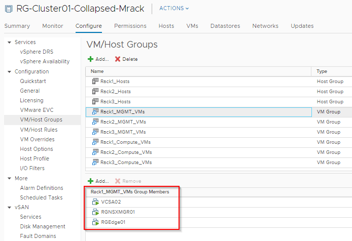
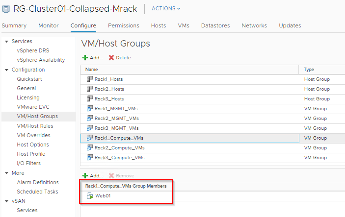
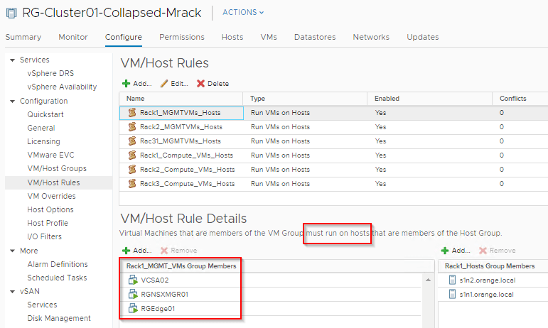
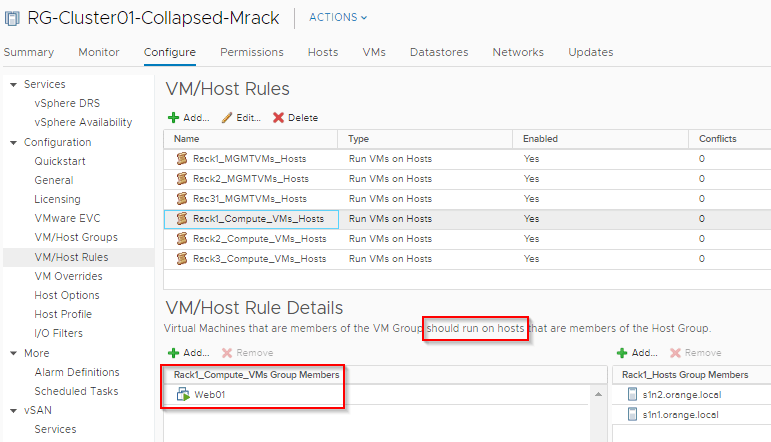
Host/VM Groups and Rack Affinity
Hosts and VMs are grouped according to their rack membership. Affinity rules are put in place to restrict VMs to their respective racks. Anything on VLAN backed networks will not have mobility across racks and as such vCenter Server, NSX-T Manager, NSX-T Edges are handled by their respective HA mechanisms at the application level in case of a rack failure. Compute VMs (Web) are on Overlay backed Segments and will failover to other racks in case of a rack failure.
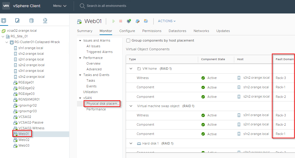
Storage
- vSAN makes up the Storage layer.
- 3 X vSAN Fault domains are created which maps to the respective racks.
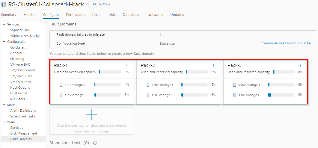
SPBM policies applied on the compute VMs will place the components across the racks to withstand a rack failure.
NSX-T Networking
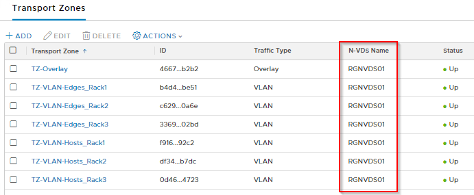
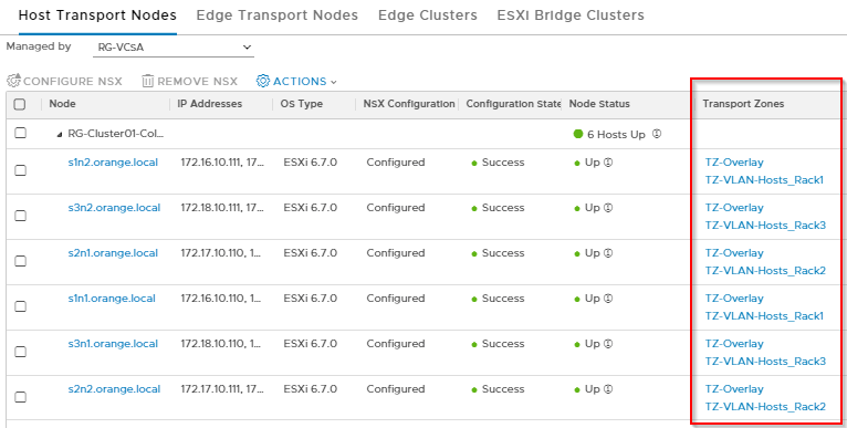
Transport Zones
We have defined an Overlay Transport zone and a number of VLAN Transport zones based on racks, all leveraging the same NVDS (RGNVDS01). Each Rack will have a separate VLAN TZ for isolation of logical segments across racks such that a VLAN LS created for hosts on one rack will not be seen by hosts on the other rack. As such all Edges will also have a dedicated VLAN TZ per rack.
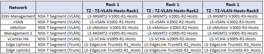
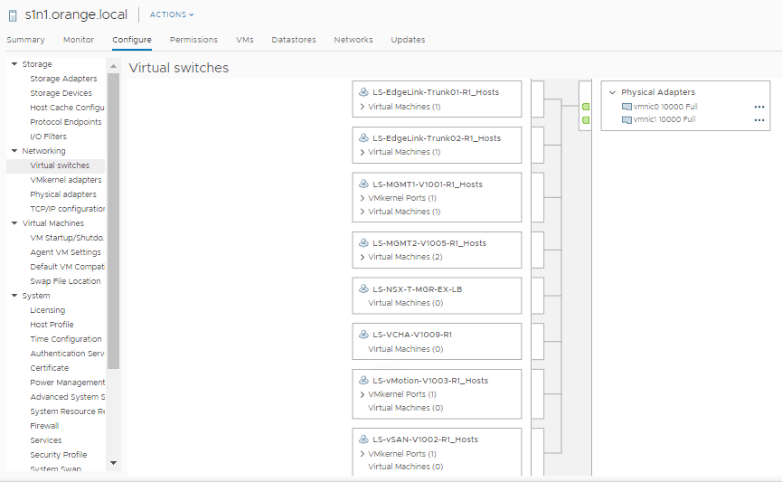
Logical Segments
We have also created a number of VLAN backed Logical segments based on VLAN Transport zones per rack. These are the Segments for Hosts.
And these are the Segments created for Edges.

Uplink Profiles
An uplink profile defines the teaming policies and the TEP VLAN. In this architecture, each rack will have separate TEP VLANs, as such we need separate Uplink Profiles for each rack (both hosts and edges).

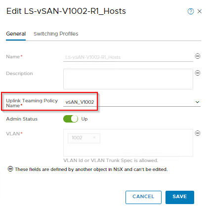
Named Teaming Policies
Optionally, we could also configure Named Teaming Policies to achieve deterministic steering of the infrastructure VLANs over specific host uplinks. Named Teaming Policies can also be configured on the Edges for deterministic eBGP peering with the Leaf Switches.
This is an example from a Rack1 profile.

Transport Node Profile
We can’t use Transport Node profile to prepare the cluster for NSX-T as we need to link multiple uplink profiles for this to happen, which is not possible. We would need to configure the hosts individually.
Edge nodes are also configured according to their rack placement. The Edge Deployment model is Single NVDS Multi-TEP attached to host NVDS Networking. To see how this can be achieved, please visit my earlier article:
By having Transport Zones at the rack level, we should see that a host on a specific rack has visibility to only those Logical Segments that are intended for that specific rack.
Tier 0 Gateway
Tier 0 Gateway is deployed in Active-Active mode with six uplinks , two uplinks each via separate edge nodes.
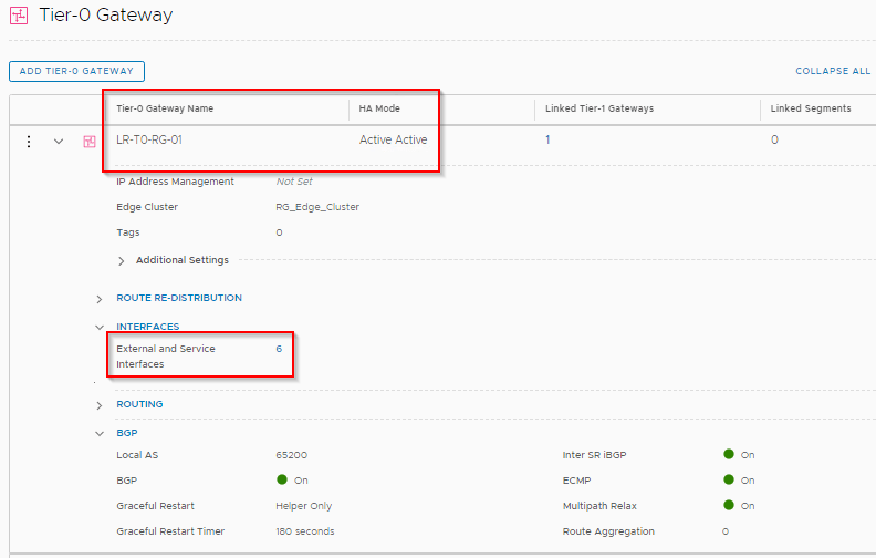
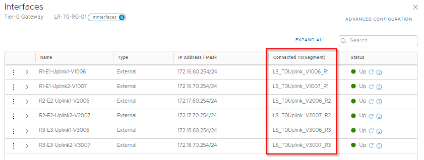
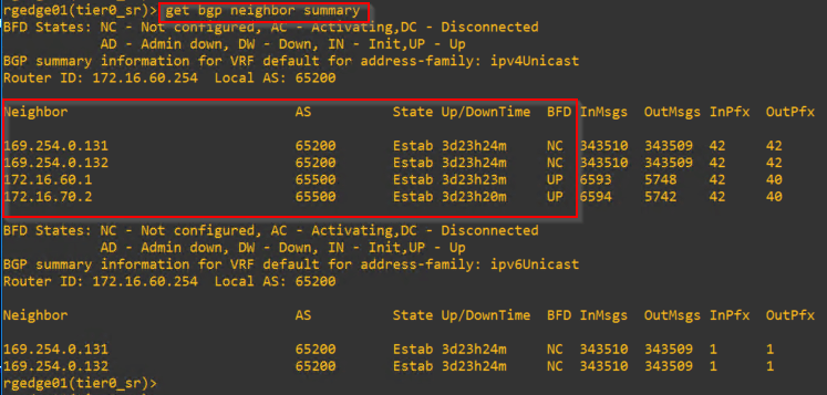
Each Edge node has 2 eBGP peering with the Leaf Switch on the respective rack, making a total of 6 eBGP peerings.

Edge nodes also establish an Inter-SR iBGP peering with the other Edge SR Constructs. To see how this works, please visit:
https://vxplanet.com/2019/07/12/nsx-t-tier0-inter-sr-routing-explained/
https://vxplanet.com/2019/08/22/nsx-t-tier0-inter-sr-ibgp-ecmp-explained/
With Route Redistribution on T0 Gateway enabled, we should see the Overlay subnets getting advertised to the Leaf switches.
We are now done with the architectural discussion. We will continue in Part 2 to configure NSX-T Loadbalancer for the NSX-T Manager cluster and simulate a rack failure.
I hope the article was informative.
Thanks for reading
Continue Reading? Here is the second part:
https://vxplanet.com/2020/03/26/using-nsx-t-loadbalancer-for-the-nsx-t-management-cluster-part-2/

HA VIP is not the correct term for the build in VIP in the NSX-T manager appliances. HA VIP is a feature in the NSX-T Edge node, typically used with static routing.
The correct term is called just VIP or Cluster VIP:
https://docs.vmware.com/en/VMware-NSX-T-Data-Center/2.5/installation/GUID-A8DF27CC-B3A6-45F2-856D-4278A7DBC98E.html
Oh yes, Thanks for pointing out that Oliver.
Cheers.
Hari