
NSX-T introduced a Single NVDS Multi-TEP design for the Edge nodes in version 2.4, with recommendation to use from version 2.5 onwards. With this new design, we could now achieve better load balancing for the overlay traffic as well as have a consistent deployment model for both VM and BM edge form factors. A consistent deployment model would also mean that migrating an Edge Cluster from VM formfactor to Baremetal would be more easy than before.
ICYMI, I wrote an article previously on the deployment and configuration of Single NDVS Multi-TEP Edges on vSphere DVS, you can find it below:
The above Edge deployment works in scenarios like:
- Edges deployed on a dedicated Edge Host cluster leveraging vSphere DVS (The Edge Host Cluster is not prepared for NSX-T)
- Edges deployed on a shared Management & Edge Host cluster leveraging vSphere DVS (The Host Clusters are not prepared for NSX-T)
- Edges deployed on Shared Compute and Edge Host cluster leveraging vSphere DVS. The hosts will have 4 pNICs where 2 pNICs connect to vSphere DVS and the other 2 connect to host NVDS.
In a scenario where we deploy Edges on a Shared Compute and Edge Host Cluster with 2 pNICs, like an NSX-T Workload Domain in VCF, we would need to connect the Edge VM Uplinks to host VLAN NVDS networking and adopt either:
- Multi-NVDS Single-TEP design (as described in my earlier post)
https://vxplanet.com/2019/07/08/deploying-and-configuring-nsx-t-edges-on-n-vds-networking/
- or Single-NVDS Multi-TEP design (below)
In this article we will walk though the deployment and configuration of Single NVDS Multi-TEP Edges on 2 pNIC host NVDS networking where all the infrastructure host networking is migrated to NVDS and is completely decoupled from vCenter DVS.
Single NVDS Multi-TEP Edge VM Architecture

Environment Details
We will deploy the Edge VMs on a 4-node shared Compute and Edge Host Cluster prepared for NSX-T.
- A shared Compute and Edge cluster with 4 X Dell EMC Poweredge R640 servers as ESXi hosts. They are prepared for NSX-T and hence are NSX-T Transport nodes and have NVDS deployed
- 2 X 10G host networking connected to Dell EMC Networking S4048-ON switches in VLT (No LACP)
- Single NVDS with uplinks bound to the 2 pNICs
- NSX-T 2.5 with a 3 node management cluster on a dedicated Management Host cluster
As a Tip, before deploying NSX-T, make sure to check the VMWare Interoperability matrix to ensure that the version of vSphere ESXi is compatible. For NSX-T 2.5, check the below link:
We will deploy the NSX-T Edges using the OVA file. Edges are deployed with 4 vNICs. This is how we use the vNIC binding for a single NVDS Multi-TEP design.
- Management (named as eth0) – Connected to the ‘LS_Management_V10’ Logical Segment on Host NVDS (VLAN 10)
- FastPath interfaces (fp-eth0 & fp-eth1) – They are uplinks to the Edge VM NVDS and attach northbound to separate Trunk Logical Segments on Host NVDS Networking. The Trunk Logical Segments are tagged on VLANs 60,70 & 80.
- The last vnic is disconnected in this case.
These are the VLAN details:
VLAN 10 – Management
VLAN 40 – Host Overlay Transport (TEP)
VLAN 60 – VLAN Uplink for the Edges (T0) to eBGP peer with the Leaf Switches
VLAN 70 – VLAN Uplink for the Edges (T0) to eBGP peer with the Leaf Switches
VLAN 80 – Edge Overlay Transport (TEP).
Note : For Edges deployed on Host NVDS, it is mandatory to have separate VLANs for Host TEP and Edge TEP network.
Creating the Transport Zones
We will create 3 Transport Zones on a Single NVDS ‘NVDSStaging01’:
- An Overlay TZ where both the ESXi Compute Transport Nodes and Edge Transport Nodes are a part of (TZ_Overlay_Staging)
- A VLAN TZ for the Compute ESXi Transport nodes (TZ_Host_VLAN_Staging)
- A VLAN TZ for the Edge Transport nodes (TZ_Edge_VLAN_Staging)
We use different VLAN TZ for the Host and Edges to isolate the VLAN Logical Segments from each other based on intended purposes. For eg:
- Edges doesn’t need to see the Infrastructure VLAN LS intended for the host networking like vSAN, vMotion etc
- Hosts doesn’t need to to see Tier0 VLAN Uplink LS created on the Edges.

Creating Edge Uplink Profile with Deterministic Peering for the Uplinks
Since Edges are deployed on Host NVDS, Edge TEP should be on a separate VLAN (VLAN 80) from the Host TEP (VLAN 40). We also create separate Named Teaming Policies for the Edge Uplinks – VLAN70_Uplink & VLAN60_Uplink using Failover Teaming Policy with alternating Active Uplinks

The Edge VLAN Transport Zone is updated with the Named Teaming Policies so that they can be applied to the Tier0 Gateway Uplinks when we create them later.

Creating Host Uplink Profile with Deterministic Steering for the Infrastructure & Trunked VLANs
Achieving Deterministic Steering for the Infrastructure VLANs is covered in my earlier post, just in case you are interested you can read it here:
https://vxplanet.com/2019/09/25/achieving-deterministic-peering-using-nsx-t-named-teaming-policies/
For this article, we will discuss deterministic steering only for the Trunk Logical Segments that we create in the next step.
We create two Named Policies for the Trunk Logical Segments with alternating Active and Standby Uplinks. The Host Uplinks bound to this Uplink Profile connect to separate VLT peer switches.

The Host VLAN Transport Zone is updated with the Named Teaming Policies so that they can be applied to the Trunk Logical Segments when we create them later.

Configuring the Host NVDS VLAN Trunk Logical Segments
We would need to create two VLAN Logical Segments on the Host NVDS Networking to allow multiple VLAN tags from the Edge NVDS to pass though. They are created on Transport Zone ‘TZ_Host_VLAN_Staging’ so that they are visible only to the ESXi Transport Hosts. As mentioned in the VLAN details above, this trunk Logical Segment should allow tags 60, 70 & 80. The Trunk Logical Segments will have the below Named Teaming policy set on the ESXi hosts:
LS_Trunk01_MTEPEdge – Active Uplink: vmnic0 and Standby Uplink: vmnic1
LS_Trunk02_MTEPEdge – Active Uplink: vmnic1 and Standby Uplink: vmnic0

The Trunk Logical Segments should now appear attached to the Host NVDS.

Let’s apply the Named Teaming Policy to the Trunk Logical Segments


Deploying the first Edge VM from OVA template

Select the proper Sizing for the Edge nodes depending upon the use case. For Eg: for Enterprise PKS, we need the Large Form factor.


Select the vNIC networking on the host NVDS
Network 0 : LS_Management_V10 (VLAN10)
Network 1 : LS_Trunk01_MTEPEdge (Trunk LS on Host NVDS)
Network 2 : LS_Trunk02_MTEPEdge (Trunk LS on Host NVDS)
Network 3 : Select a dummy host network here. This is not used in this design and will be removed post-deployment.


Set the hostname, IP Parameters, DNS, NTP and Passwords.

Post deployment, make sure to remove the forth vNIC
Power on the Edge VM from vCenter and wait for the console login screen.
Deploying the Second Edge VM from OVA template
The procedure is similar except that the management IP is different.
Joining the Edge VMs to the NSX-T Management Plane
Generate the Certificate api thumbprint from one of the NSX-T managers and register both Edge VMs to the Management Plane.


They should now appear under Edge Transport Nodes in NSX-T Manager.

Configuring Edge nodes as NSX-T Transport Node
We will configure Edge nodes for the below Transport Zones:
- TZ_Overlay_Staging (Overlay)
- TZ_Edge_VLAN_Staging (VLAN)

As said earlier, Edge TEPs are on VLAN 80 which is separate from Host TEP. We will define a Pool for the Edge TEP on VLAN 80.

We will have only a single NVDS for the Edge VM as both Transport zones leverages the same NVDS.

The Configuration should now succeed.

Creating the Edge Cluster
Now we will add both Edge VMs to the Edge Cluster.

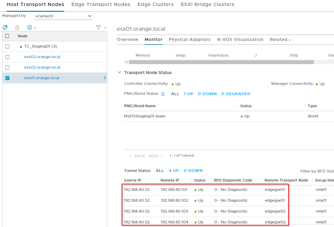
Verify that the BFD tunnel between the Edge nodes are up.

Verifying the Edge TEP
Let’s see whether Edge VMs have two TEP IPs assigned and that they are reachable.


SUCCESS!!!
Creating the Tier0 Uplink VLAN Logical Segments
We need to create two Uplink VLAN Logical Segments for the Tier 0 Gateway Uplinks. Note that this should be created on the same VLAN Transport Zone on which the Edge VMs are configured (TZ_Edge_VLAN_Staging). This Logical Segments are not seen by the Host Transport nodes as they are on different VLAN TZ.
The VLAN Logical Segment should have the respective VLAN Identifier (60 or 70) as the tagging is applied by this Logical Segment.

Deploying a Tier0 Gateway and adding Uplinks
We will deploy a Tier0 Gateway in Active-Active mode. There are 2 SR Constructs with two uplinks each, so a total of 4 Uplinks for the T0 Gateway.

Here are the T0 Uplink details:
- Uplink1_V60 – on VLAN 60 via Edge node 1
- Uplink2_V70 – on VLAN 70 via Edge node 2
- Uplink3_V60 – on VLAN 60 via Edge node 2
- Uplink4_V70 – on VLAN 70 via Edge node 1

Let’s connect to the SR Constructs on each Edge node and verify northbound reachability.

Success!!! Edge node 1 can reach the Default Gateway via both VLANs 60 & 70.

Success!!! Edge node 2 can reach the Default Gateway via both VLANs 60 & 70.
I’ve now deployed a Tier1 Gateway and attached a VM on ESXi host 1 to an Overlay LS on the Tier1 Gateway. The T0 DR Construct should be now available on all the transport nodes and we should see a geneve tunnel established from this Transport host to both the Edges for this VNI.

I have also completed the BGP configuration on the T0 Gateway and advertised the necessary networks. Let’s do a connectivity test from the VM to the Default Gateway on the external Leaf switches.

Success!!! This validates the deployment. I hope this article was informative.
Thanks for reading.

Very nice design. Excellent article!
Thanks Teddy
Hi,
it’s really a great post. I am learning NSX-T recently. I have some issues when I am deploy the NSX-T, the edge tep ip addresses to ESXi host transport node ip addresses are down.
Noticed that you have configured a gateway “192.168.101.100” in Edge TEP IP Pools in part “Configuring Edge nodes as NSX-T Transport Node”. Just want to know, is this gateway “192.168.101.100” applied and configured by NSX-T automatically? or this gateway should be configured manually and the gateway should have already been existed?
Thanks, in advance.
Hi Xing, the Gateway I used was 192.168.80.100 (on subnet 192.168.80.0/24) which is a VLAN backed Logical Segment on Host networking. This gateway is configured on the ToR and should already exist before configuring the Edges.
One reason for TEP Tunnels being down might be related to having same VLANs on hosts and Edges. If Edges are attached to NVDS on Compute Hosts, they should be on different TEP VLANs
Thanks
After “Creating the Tier0 Uplink VLAN Logical Segments” wont you need to specify uplink teaming policy?
Hello Ozer, Yes we need to apply the Named Teaming Policies to this T0 VLAN Logical Segments as well.
Hello Hari,
Thank you for sharing, quick question.
We have 4 Pnic’s on the hosts and, 2 nics are being used production workload and the other 2 for vSAN, vmotion, mgmt etc.
Can we pull one Pnic from MGMT and install NSX-T and move the other Pnic to nsx-t? as we want our VLAN traffic to be managed by vDS.
Hi Chandra, in a supported configuration, Yes we could have one DVS that handles all the VLAN traffic – this will handle all the infra traffic for MGMT, vSAN , vMotion, Edge Uplinks etc. The other 2 pnics can be migrated to an NVDS which will handle all overlay based traffic.